Vacuum supply system

a vacuum pump and supply system technology, applied in the direction of fluid couplings, combustion air/fuel air treatment, couplings, etc., can solve the problems of reducing the life of the pump, increasing fuel costs, and inability to purge flow, so as to shorten the duration of the vacuum pump operation and improve the fuel economy and emissions of the vehicl

Inactive Publication Date: 2011-06-28
FORD GLOBAL TECH LLC
View PDF18 Cites 44 Cited by
  • Summary
  • Abstract
  • Description
  • Claims
  • Application Information

AI Technical Summary

Benefits of technology

[0009]In this way, a purge flow may be drawn to an engine intake, in the presence or absence of engine boost, without requiring constant purge pump operation. Further, the purging operation may be performed independent of a blow-by gas flow. Specifically, in the absence of boost, an engine intake manifold negative pressure may be used to draw a purge flow, while a purge pump may be used to draw a purge flow in the presence of boost. Additionally, a vacuum may be drawn at the ejector coupled downstream of the pump during every purging operation. Specifically, by pumping the purge flow through an ejector before delivering purged fuel vapors to the engine intake, a vacuum may be generated at the ejector during boosted conditions, which may be advantageously used for actuating additional vacuum actuators. Consequently, the need for dedicated vacuum pumps for the vacuum actuators may be reduced. Alternatively, the purge flow driven vacuum may be used in addition to a dedicated vacuum pump, enabling the use of a smaller vacuum pump for the vacuum actuator and / or a shorter duration of vacuum pump operation. By enabling purging and vacuum actuation under most engine operating conditions, vehicle fuel economy and emissions may be improved.

Problems solved by technology

However, the inventors herein have recognized potential issues with such an approach.
Thus, due to dependence on pump operation for purging, during conditions where pump operation is limited or restricted, a purge flow may not be possible.
Additionally, the need for constant pump operation during purging may add to fuel costs while decreasing pump life.
Thus, during purging conditions when a flow of blow-by gases to the intake is not desired, or not available, a purging operation may not be performed.
Thus, an alternate vacuum actuator, such as a power brake, may not be operated using the ejector vacuum during a purging operation.
As such, this may increase component cost.

Method used


Image

  • Vacuum supply system
  • Vacuum supply system
  • Vacuum supply system

Examples


embodiment 200

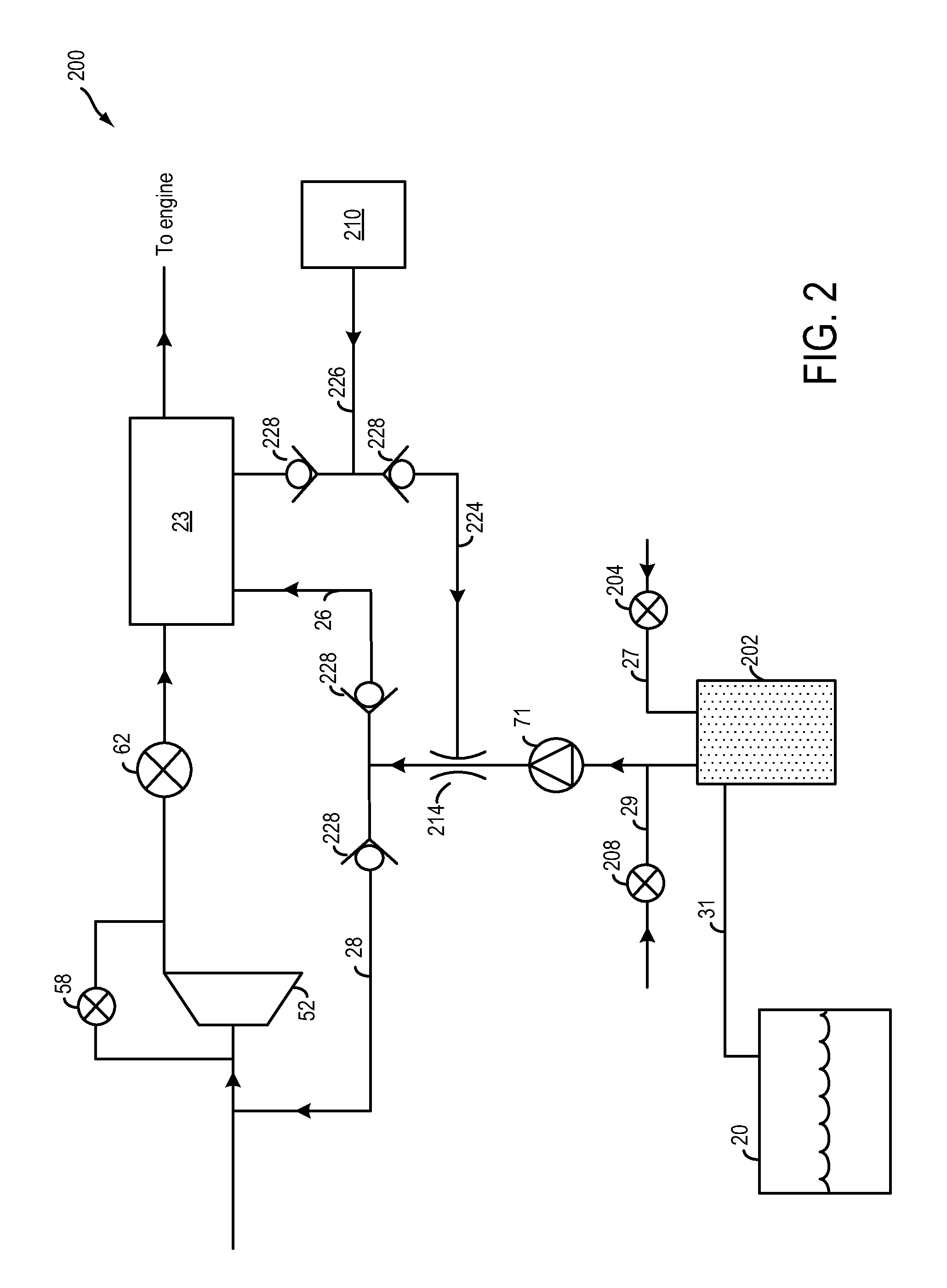
[0023]As depicted in FIG. 2, embodiment 200 of fuel vapor recovery system 22 includes a fuel vapor retaining device, depicted herein as fuel vapor canister 202. Canister 202 may be filled with an adsorbent capable of binding large quantities of vaporized HCs. In one example, the adsorbent used is activated charcoal. Canister 202 may receive fuel vapors from fuel tank 20 through conduit 31. While the depicted example shows a single canister, it will be appreciated that in alternate embodiments, a plurality of such canisters may be connected together. Canister 202 may communicate with the atmosphere through vent 27. Canister vent valve 204 may be located along vent 27, coupled between the fuel vapor canister and the atmosphere, and may adjust a flow of air and vapors between canister 202 and the atmosphere. In one example, operation of canister vent valve 204 may be regulated by a canister vent solenoid (not shown). For example, based on whether the canister is to be purged or not, th...

embodiment 300

[0028]FIG. 3 shows an alternate embodiment 300 of the fuel vapor recovery system. Herein, the one or more ejectors include a first ejector 214 coupled to (first) vacuum actuator 210, positioned downstream of purge pump 71, and a second ejector 314, coupled to first ejector 214, and further coupled to the (first) vacuum actuator 210, positioned downstream of purge pump 71 and upstream of compressor 52, along second conduit 28. In one example, second conduit 28 may be controlled with a solenoid valve or other valve type to improve turbocharger spin-up. In this way, second ejector 314 may be included to further deepen engine vacuum. In an alternate embodiment, first ejector 214 may be coupled to a first vacuum actuator while second ejector 314 may be coupled to a second actuator.

[0029]It will be appreciated that while the embodiments of FIGS. 2-3 illustrate a dual path system (into the engine intake manifold and the engine air inlet), in alternate embodiments, a purge flow may be direc...


PUM


Abstract

A method of operating a boosted engine system is described in which an ejector coupled with a fuel vapor purging system can generate vacuum during both purging and non-purging conditions, and during both boosted and non-boosted conditions. The vacuum can therefore be used to power vacuum actuated brakes, and/or other vacuum actuators, irrespective of the purging conditions, and irrespective of boost levels.

Description

FIELD[0001]The present description relates to methods and systems for providing a vacuum for various actuators, including a power brake and a fuel vapor recovery system, in a vehicle with a boosted internal combustion engine.BACKGROUND / SUMMARY[0002]Vehicles may be fitted with emission control systems wherein vaporized hydrocarbons (HCs) released from a fuel tank (for example, during refueling) are captured and stored in a fuel vapor canister packed with an adsorbent. At a later time, when the engine is in operation, the evaporative emission control system may use a vacuum (or pressure) to purge the vapors into the engine intake manifold for use as fuel. The purge flow vacuum (or pressure) may be generated by one or more pumps and / or ejectors.[0003]One example approach for providing sufficient vacuum for a fuel purge flow is illustrated by Kakimoto et al. in US 2006 / 0196482 A1. Herein, blow-by gas and purge gas are delivered to the engine intake together. Specifically, blow-by gas is...

Claims


Application Information

Patent Timeline
Patent Type & Authority Patents(United States)
IPC IPC(8): F02M33/04
CPCF02B37/127F02M25/089F02M25/0836F02B37/186Y02T10/144F02B37/162Y02T10/12
Inventor PURSIFULL, ROSS DYKSTRA
Owner FORD GLOBAL TECH LLC
Why Eureka
Try Eureka