System for removing oil from a water surface

Inactive Publication Date: 2011-06-28
KOSEQ
View PDF18 Cites 1 Cited by
  • Summary
  • Abstract
  • Description
  • Claims
  • Application Information

AI Technical Summary

Benefits of technology

[0007]The object of the present invention is to provide an improved skimming system by means of which the floating layer on the water surface can be removed in a more effective manner.
[0009]The 
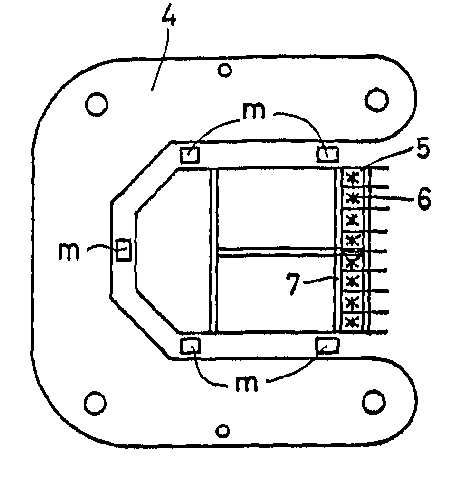
advantage of the skimming system according to the invention is that the collecting container can be exchanged and be substituted for another collecting container. This is furthermore advantageous in particular when the removal unit is provided with floating layer removal means that are generally attached to the collecting container, such as brushes (usually driven brushes), paddles, discs, pumps and / or overflow means. The fact is that it is possible in that case to obtain the degree of flexibility as regards the most optimum way of handling the removal of the oil slick that is very important in practice. It has become apparent that the effectiveness of the oil removal operation depends inter alia on factors such as: the nature and the composition of the floating layer, the viscosity, the layer thickness, the direction of the current, the velocity at which the floating layer moves, the degree to which the layer is mixed with water, the amount of air bubbles in the oil, the pumpability, and the local conditions, such as the waves, the temperature, the force and the direction of the wind, the environment etc. When the present invention is used, the desired floating layer removal means can be advantageously selected by exchanging the collecting container to which said means are already attached. Moreover, the aforesaid factors considered to be of paramount importance for the local situation can be optimally taken into account when making the aforesaid selection.
[0010]Exchanging the collecting container with removal means attached thereto for the purpose of carrying out an oil removing operation geared to the situation at hand is not only easy, but it is also cheaper and can be carried out in less time on site than detaching the old floating layer removal means and fitting the new one, which was previously necessary. A quick exchange in particular of the floating layer removal means in question is moreover important in order to be able to quickly repair any malfunctions on site.
[0012]If the collecting container is vertically adjustable, the removal means attached thereto are automatically adjusted for height as well upon vertical adjustment thereof. Said vertical adjustment not only makes it easier to detach and exchange the collecting container, but in addition the floating layer removal means can be moved to a desired depth in or below the floating layer so as to realise an optimum removal of the floating layer, taking into account the aforesaid local factors. In all the situations in which brushes, paddles, discs and / or overflow means provided with an overflow wall are used, said vertical adjustment is advantageous in practice.
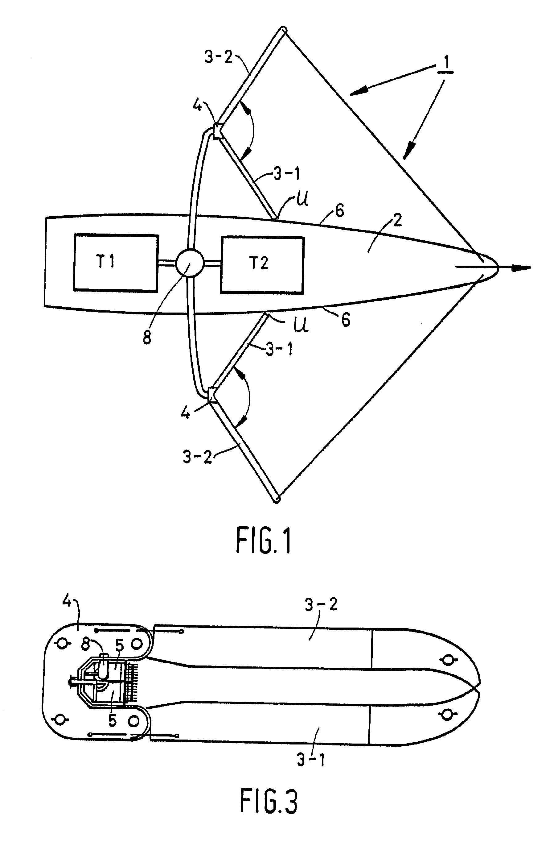
[0016]The turbulences in the collected oil that lead to the aforesaid undesirable mixing are often caused by the movement both of the vessel, which displaces comparatively much water, and of the guide elements, which are usually supported on pontoons and which have less draught than the vessel. The presence of an excess of air in the oil may also be caused by the fact that the collected oil is sucked in and forced out with too much force, however, which also has an adverse effect on the effectiveness. If the collecting point of the oil and the discharge point are located too close to the side wall of the vessel, this may lead to the aforesaid turbulence and short waves at the location of the collecting point under certain circumstances, for example sailing against the current, incoming wind or (overly) rapid skimming. For that reason the collecting point must be provided at the location on the guide element where the extent to which water and / or air are mixed with the floating layer is minimal. The idea is that the interface between oil and water and / or air will only be affected to a small extent and will still be reasonably flat when the location of the collecting point or intake point is suitably selected, so that oil can be removed in an effective manner. In addition, the dimension of the oil layer to be pumped out will be known more precisely in that case and it will be easier to gear the vertical adjustment of the system thereto, as a result of which the level efficiency will be enhanced even further.
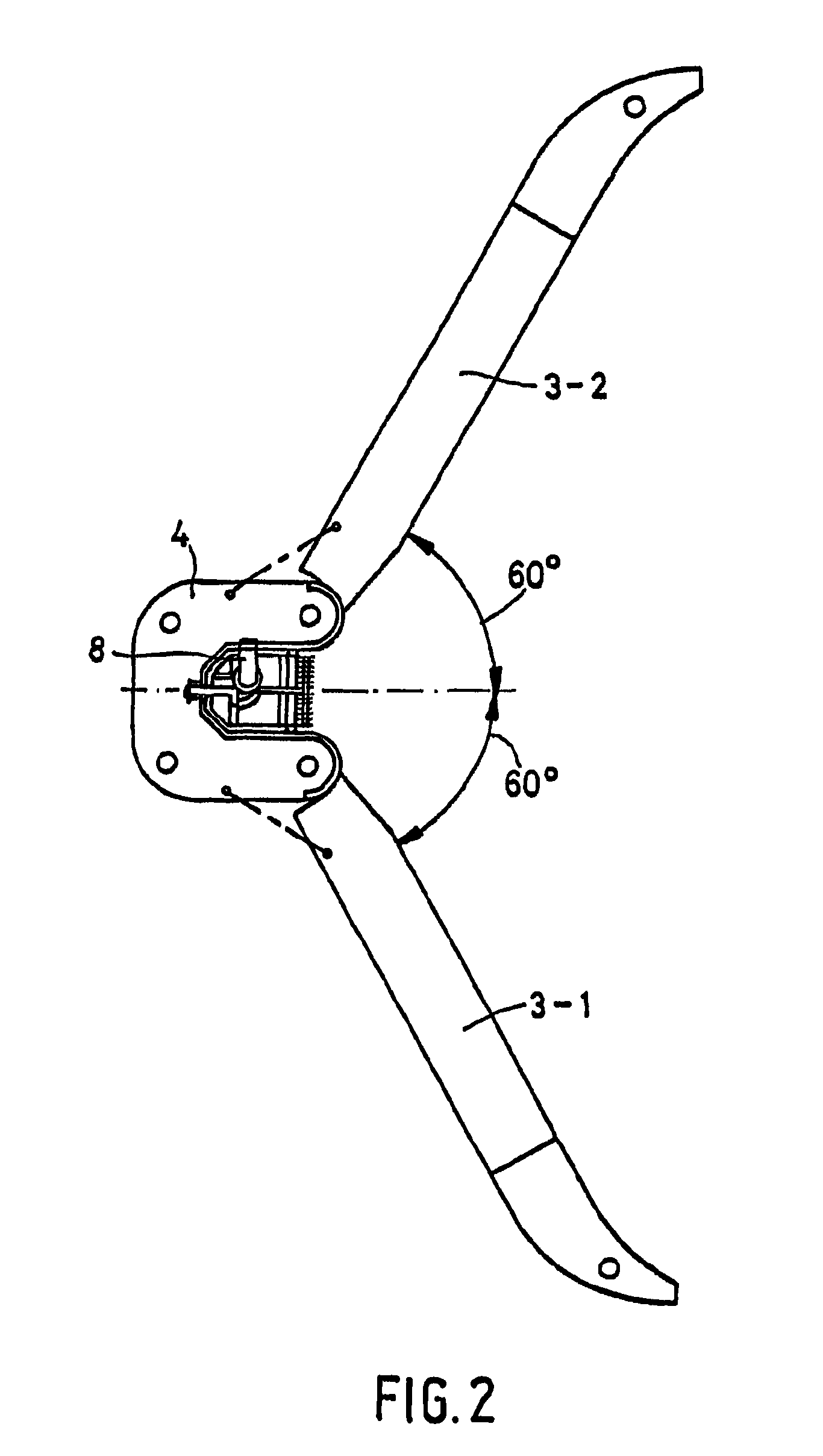
[0020]The advantage of this is furthermore that a compact skimming system that can be rendered operational in a short time is obtained, which system is nevertheless capable of spanning a wide oil removal area. In addition, collecting containers may be disposed at several locations in the guide elements.

Problems solved by technology

A drawback of the known system and the known method of removing oil from the water surface is that they are not always very effective in optimally removing various types of oil in practice.

Method used


Image

  • System for removing oil from a water surface
  • System for removing oil from a water surface
  • System for removing oil from a water surface

Examples


Embodiment Construction

[0028]FIG. 1 schematically shows a skimming system 1, in this case comprising a vessel 2 and one or more series of floating layer guide elements 3-1, 3-2, which are coupled together and to the vessel 2. It is also possible to tow said one or more of series of guide elements 3 beside or behind the vessel 2 by means of tow cables or, for example in case of contamination of a waterway, to fix a system of guide elements 3 to the banks by means of tow cables, in which case a propulsion vessel is not needed but advantageous use is made of the current in the water. In FIG. 1, the vessel 2 moves the skimming system 1 provided with the guide elements through the water in the direction indicated by the arrow, and a contaminating substance that floats on the surface, e.g. oil, to be referred to below as “floating layer”, collects between the guide elements 3-1 and 3-2. In a special embodiment, the shell of the vessel may form part of the floating layer guide elements 3 in that the vessel 2 mov...


PUM

PropertyMeasurementUnit
Angleaaaaaaaaaa
Concentrationaaaaaaaaaa
Depthaaaaaaaaaa

Abstract

A skimming system for removing a floating layer from a water surface. The skimming system includes at least one guide element that is movable relative to the floating layer, which guide element includes at least one unit that catches the floating layer. The at least one removal unit includes at least one collecting container that is detachably attached to the guide element. The collecting container is furthermore vertically adjustable, so that it is not only easy to detach and exchange the collecting container but that it is moreover possible to position the floating layer removal means at a desired depth in or below the floating layer. In this way an optimum removal of the floating layer can be realized. The inlet of the collecting container is present at a location where the extent to which water is mixed with the floating layer is minimal.

Description

FIELD OF THE INVENTION[0001]The present invention relates to a skimming system for removing a floating layer from a water surface, said system comprising at least one guide element that is movable relative to the floating layer, which guide element is provided with at least one floating layer removal unit.[0002]The present invention also relates to a floating layer guide element for use in the skimming system.[0003]The present invention furthermore relates to the use of the skimming system in removing a floating layer containing oil, chemicals, plants or algae from a water surface.DISCUSSION OF THE BACKGROUND[0004]Such skimming systems provided with guide elements are generally known, they are used in case of calamities, for example, for removing substances, usually chemical substances such as oil or oil-like contaminations, from the water surface on which said substances form a so-called floating layer.[0005]A skimming system of the above type is known from EP-A-0 059 717. The skim...

Claims


Application Information

Patent Timeline
IPC IPC(8): E02B15/04
CPCE02B15/047E02B15/04Y10S210/923Y02A20/204
Inventor KAMPERS, GERRIT
Owner KOSEQ
Why Eureka
Try Eureka