Can stack linear actuator

a linear actuator and stacking technology, applied in the direction of windings, mechanical energy handling, magnetic circuit shape/form/construction, etc., can solve the problems of large stacking and concentricity of motor designs, difficult to create parts with identical dimensions, trade-offs, etc., to increase the torque output of the motor and reduce the total number of parts needed

Active Publication Date: 2011-06-28
TRITEX
View PDF8 Cites 15 Cited by
  • Summary
  • Abstract
  • Description
  • Claims
  • Application Information

AI Technical Summary

Benefits of technology

[0009]It is an object of the present invention to provide a can stack design that can more precisely control the air gap between the inner diameter of the pole plates of the stator and the outer diameter of the rotor.
[0010]It is another object of the present invention to provide an improved can-stack linear actuator motor design that reduces an air gap between an inner diameter of the stator assembly and an outer diameter of the rotor assembly to increase the torque output of the motor.
[0011]It is still another object of the present invention to reduce the total number of parts needed for assembling the linear actuator as well as the cost of tooling.

Problems solved by technology

Current can-stack motor designs have large tolerance stack-ups and concentricity issues.
Regardless of the control on the process or the accuracy of the tooling, it is difficult to create parts with identical dimensions.
When designing a can-stack motor, a trade-off occurs between cost and tolerance accuracy across multiple parts.
In order to keep the tolerance stack-up as low as possible, a tight tolerance must be held on the outer diameter of the molded bearing journal, increasing the piece price cost and complexity of the tooling.
In addition, the inner diameter of the bearing needs to be ground to minimize the tolerance stack, which also adds cost to the bearing.
Again, this creates multiple parts that have high cost and complex tooling.

Method used


Image

  • Can stack linear actuator
  • Can stack linear actuator
  • Can stack linear actuator

Examples


Embodiment Construction

[0034]The present invention relates generally to improvements in can-stack motor designs, which include an improved rotor design with an internal anti-rotation feature as well as an improved stator design. The motor design described herein also reduces the tolerance stack-up which permits a decrease in the air gap between an inner diameter of the stator assembly and an outer diameter of the rotor assembly which produces a better magnetic field and increases the torque produced by the motor.

[0035]Magnet material plays an important role in torque output, and rare earth magnet materials can be used in the motor design described herein to produce a much stronger product at a fraction of the size. These new materials make it possible to decrease the thickness of the magnet and optimize rotor size, creating new design possibilities for improving the internal components and construction of the motor.

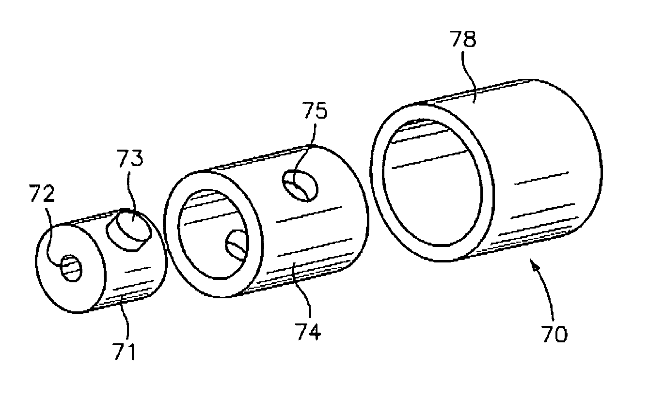
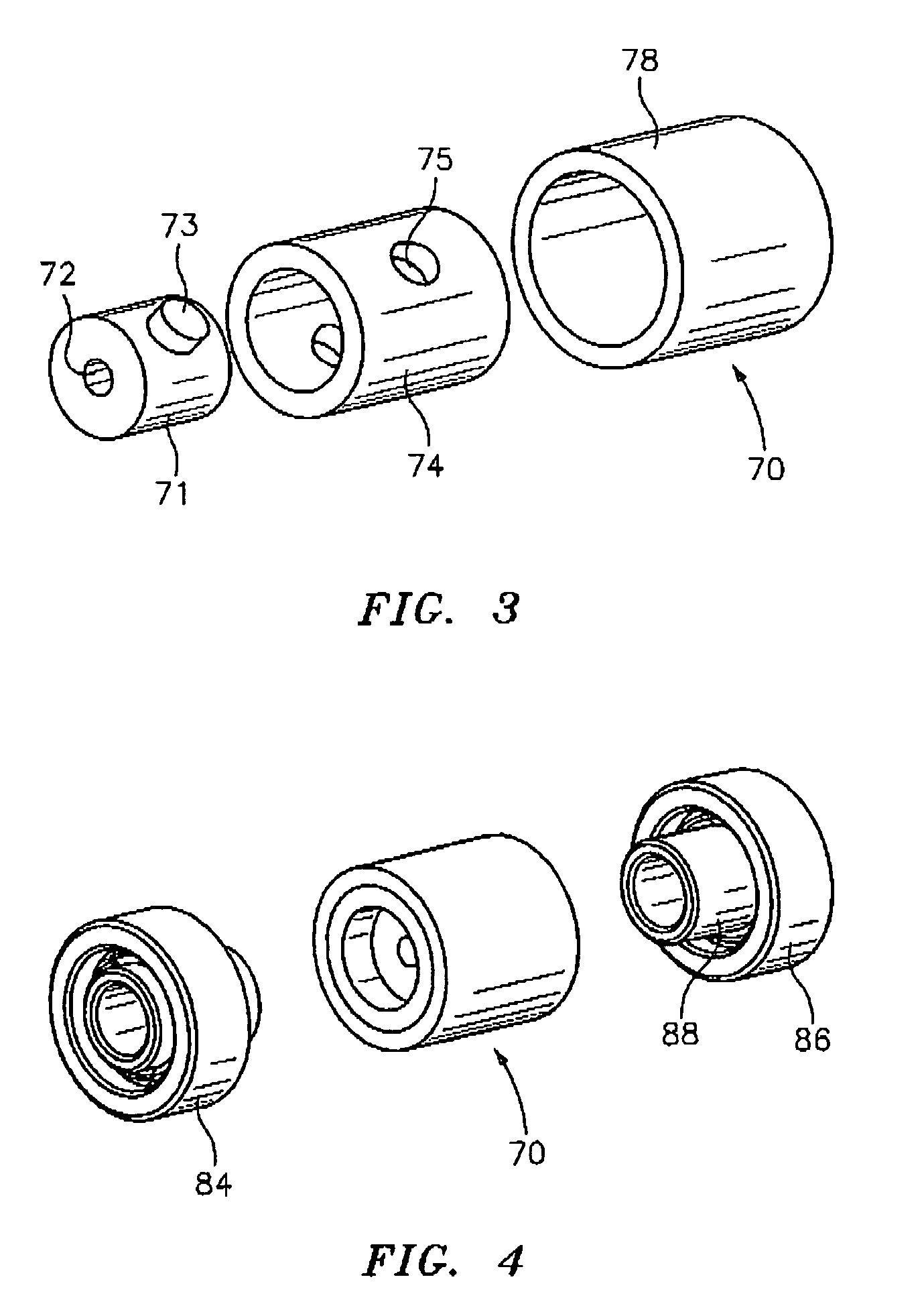
[0036]In one embodiment, the rotor assembly of the invention comprises:

[0037]a) a non-magne...


PUM


Abstract

A linear actuator motor design including a rotor assembly that has an insert molded into a non-magnetic sleeve through a plurality of openings, which is kept from rotating within the non-magnetic sleeve by at least one opening arranged along the length of the non-magnetic sleeve which corresponds to at least one tab formed by the molded material of the insert and a stator assembly having a plurality of symmetrical and interchangeable magnetic pole plates. Each of the plurality of magnetic pole plates comprises a substantially planar plate portion with a central opening therein and a plurality of prongs extending from the central opening and substantially perpendicular to the plate portion. The prongs of the plurality of magnetic pole plates create an opening that is dimensioned to receive the rotor assembly therein. A non-conductive material is the molded over the plurality of magnetic pole plates.

Description

FIELD OF THE INVENTION[0001]The present invention relates generally to improvements in motors including DC stepper motors.BACKGROUND OF THE INVENTION[0002]A linear actuator is a device that is used to perform an operation along a linear path. In one configuration, rotary motion is translated into linear motion by passing a lead screw through a threaded rotor of a rotary electric motor.[0003]A can-stack linear actuator is a specific type of motor that converts electrical energy into precise and repeatable rotational movement. Converting this rotary motion into linear motion can be accomplished in several ways. The simplest way is through an external linear motor design, in which a lead screw is rigidly fixed to the rotor, and as the rotor rotates, a linear nut external to the motor will traverse the lead screw. Another way is to use a non-captive motor design which transforms this rotary motion-using threads centrally located in the rotor. As the rotor turns and the lead screw is hel...

Claims


Application Information

Patent Timeline
Patent Type & Authority Patents(United States)
IPC IPC(8): H02K1/04
CPCH02K1/2733H02K21/145H02K7/06H02K3/525
Inventor RYAN, JUMP
Owner TRITEX
Why Eureka
Try Eureka