Image processing apparatus, magnetic resonance imaging apparatus and image processing method

a magnetic resonance imaging and image processing technology, applied in the field of image processing apparatus, magnetic resonance imaging apparatus and image processing method, can solve the problems of arbitrariness of the doctor, affecting the setting of the roi, and the result of a doctor's erroneous reading, so as to reduce the interpretation load of the doctor, improve the diagnostic efficiency and diagnostic effect, and reduce the amount of data processing

Active Publication Date: 2011-06-28
TOSHIBA MEDICAL SYST CORP
View PDF6 Cites 21 Cited by
  • Summary
  • Abstract
  • Description
  • Claims
  • Application Information

AI Technical Summary

Benefits of technology

[0026]The present exemplary embodiment has been made in light of the conventional situations, and it is an object of the present invention to provide an image processing apparatus, a magnetic resonance imaging apparatus and an image processing method which make it possible to reduce interpretation load of a doctor to improve diagnostic efficiency and diagnostic effect by selecting or compressing image information for diagnosis, such as ADC and FA.
[0027]Furthermore, another object of the present invention is to provide an image processing apparatus, a magnetic resonance imaging apparatus and an image processing method which make it possible to supply image information such as ADC and FA for diagnosis with less data processing amount.
[0031]The image processing apparatus, the magnetic resonance imaging apparatus and the image processing method according to the invention as described above make it possible to reduce interpretation load of a doctor to improve diagnostic efficiency and diagnostic effect by selecting or compressing image information for diagnosis, such as ADC and FA.
[0032]Furthermore, the image processing apparatus, the magnetic resonance imaging apparatus and the image processing method according to the invention make it possible to supply image information such as ADC and FA for diagnosis with less data processing amount.

Problems solved by technology

Accordingly, what is troubling is a doctor's erroneous reading resulted from MPG direction dependency of contrast due to T2 shine through or DWI.
Further, in the case where diffusion imaging applies to screening of a cancer in the body trunk, because of a small ADC in fat, there is a fear of false diagnosis that a fat is a cancer if a DWI which is obtained by normal processing is supplied for diagnosis.
However, there is fear that arbitrariness of a doctor affects setting of the ROI.
Because of this, there is a problem that oversight of a cancer is easy to occur.
Because of this, there is a fear that trouble happens to accumulation of evidence on a cancer diagnosis.
Thus, a problem like this has commonality to a diagnosis image imaged not only by MRI but by various image diagnostic apparatuses.
That is to say, a consequence of need to interpret extravagant image information by a doctor, is a fear that trouble occurs to not only diagnosis efficiency and diagnosis effects but also to adoption of the diagnosis method itself.
Further, there is a problem that generation of extravagant image information causes increased information processing.

Method used


Image

  • Image processing apparatus, magnetic resonance imaging apparatus and image processing method
  • Image processing apparatus, magnetic resonance imaging apparatus and image processing method
  • Image processing apparatus, magnetic resonance imaging apparatus and image processing method

Examples


first embodiment

1. First Embodiment

1-1. Constitution and Function

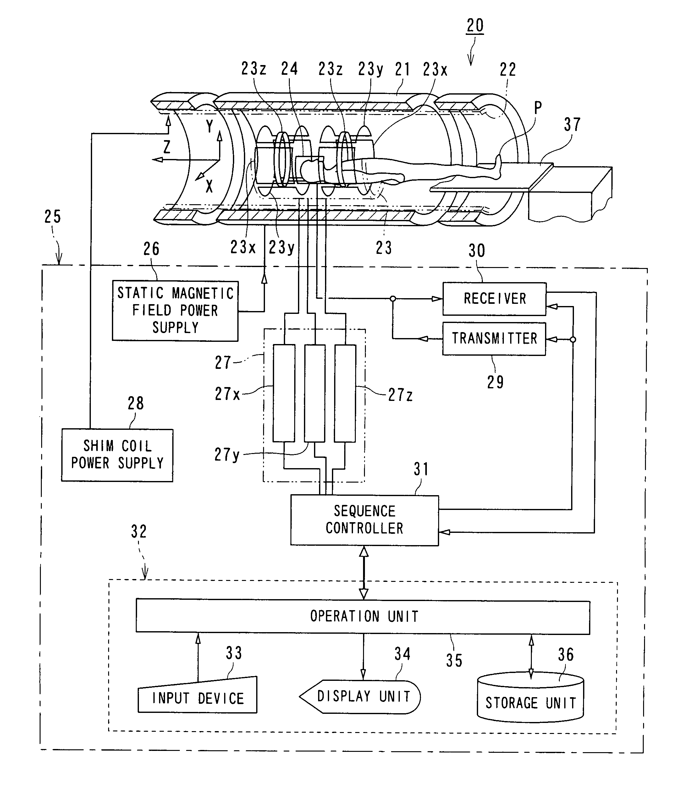
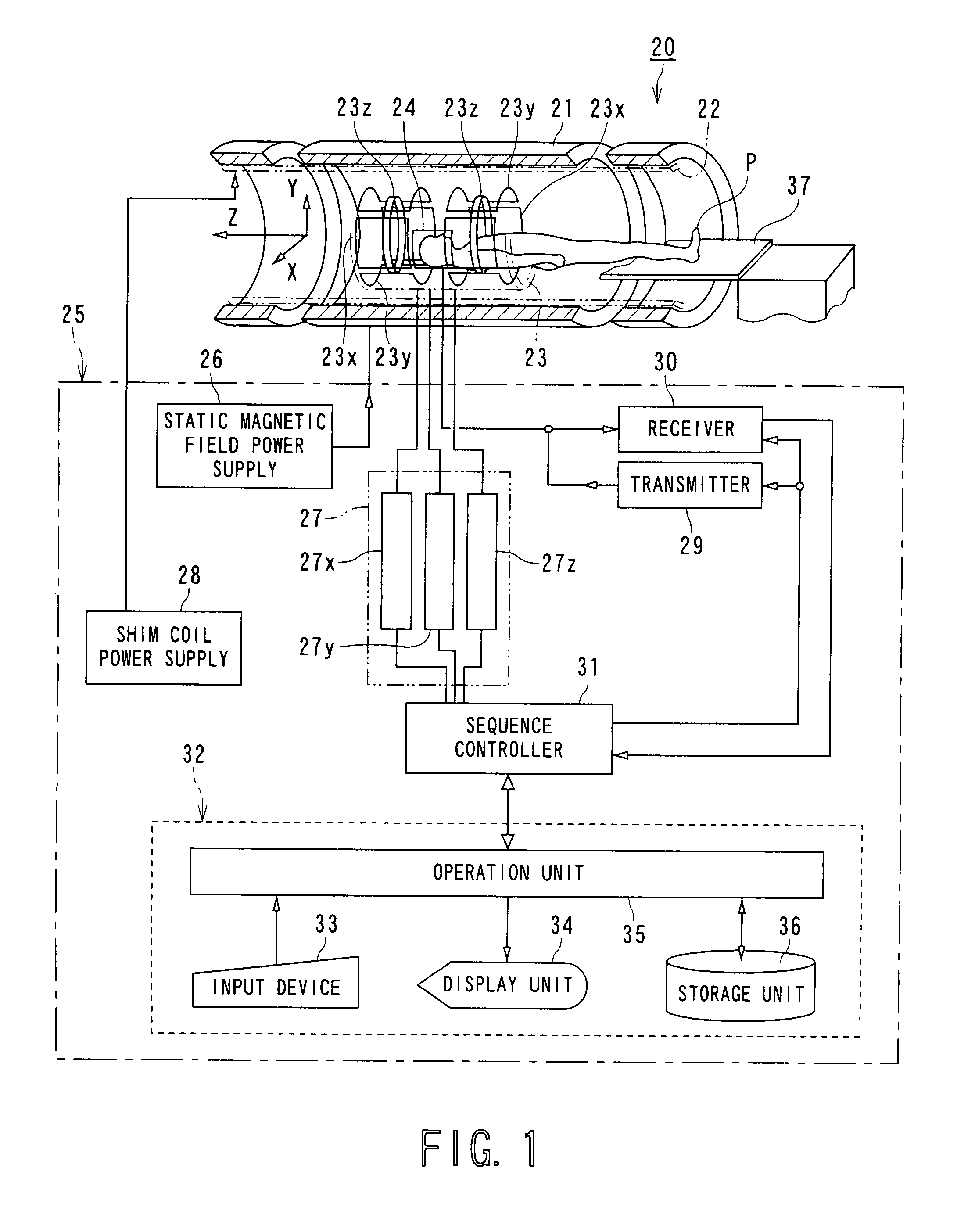
[0049]FIG. 1 is a block diagram showing a magnetic resonance imaging apparatus according to a first embodiment of the present invention.

[0050]A magnetic resonance imaging apparatus 20 includes a static field magnet 21 for generating a static magnetic field, a shim coil 22 arranged inside the static field magnet 21 which is cylinder-shaped, a gradient coil 23 and a RF coil 24. The static field magnet 21, the shim coil 22, the gradient coil 23 and the RF coil 24 are built in a gantry (not shown).

[0051]The magnetic resonance imaging apparatus 20 also includes a control system 25. The control system 25 includes a static magnetic field power supply 26, a gradient power supply 27, a shim coil power supply 28, a transmitter 29, a receiver 30, a sequence controller 31 and a computer 32. The gradient power supply 27 of the control system 25 includes an X-axis gradient power supply 27x, a Y-axis gradient power supply 27y and a Z-axis gradient p...

second embodiment

2. Second Embodiment

2.-1 Constitution and Function

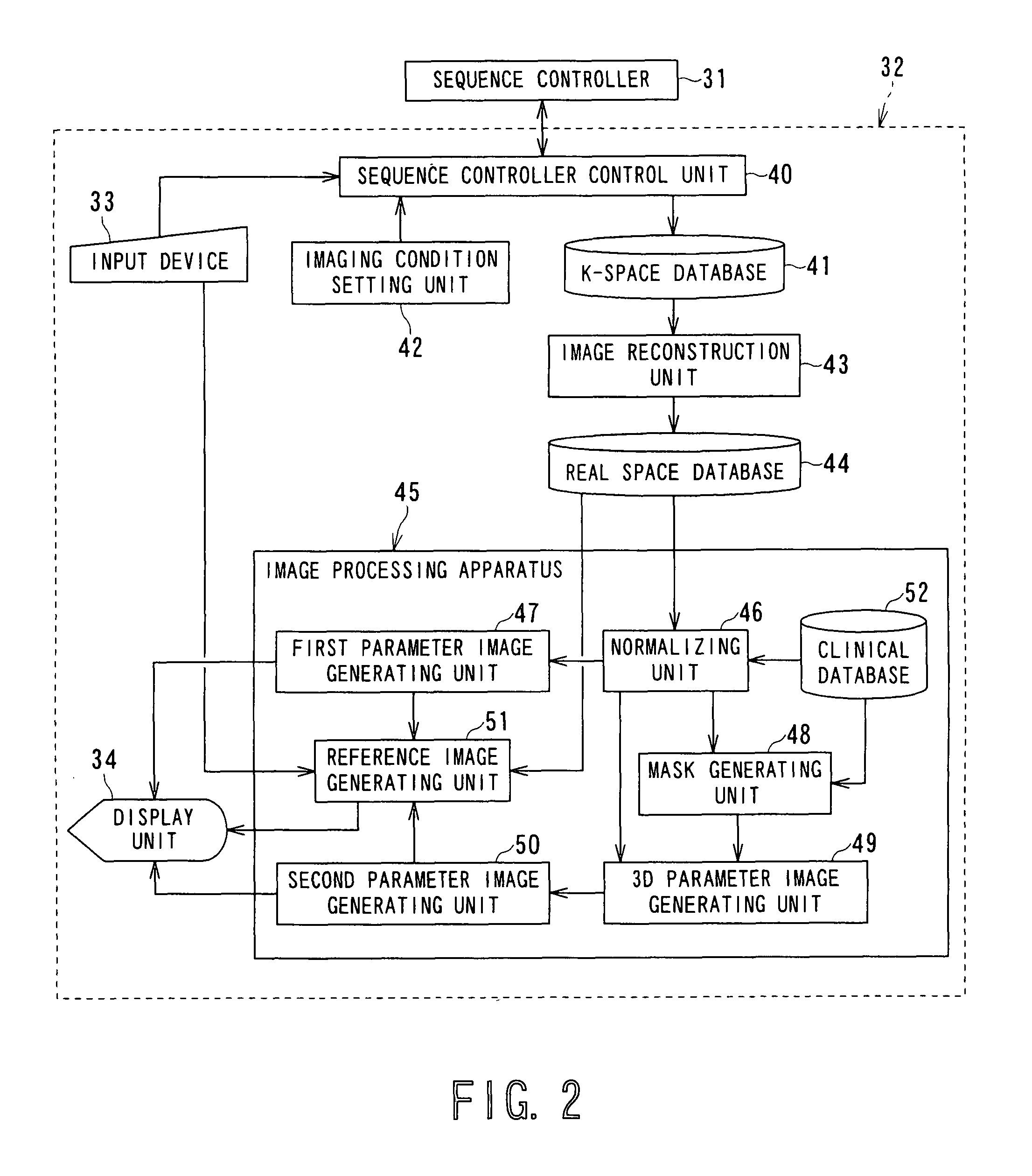
[0175]FIG. 7 is a functional block diagram of an image processing apparatus included in a magnetic resonance imaging apparatus according to a second embodiment of the present invention.

[0176]A magnetic resonance imaging apparatus 20A is different from the magnetic resonance imaging apparatus 20 shown in FIG. 1 in detail functions of an image processing apparatus 45A formed in the computer 32. Other structures and operations are substantially the same as in the magnetic resonance imaging apparatus 20 shown in FIG. 1. Therefore, only a functional block diagram of the image processing apparatus 45A is shown and the same reference numerals are used for similar components as in FIG. 2 with omitting description of equivalent functions.

[0177]The image processing apparatus 45A includes a normalizing unit 46, a first parameter image generating unit 47A, a mask generating unit 48A, a second parameter image generating unit 50A, a reference imag...


PUM


Abstract

An image processing apparatus includes a storage unit, a specifying unit, a calculation unit and a display unit. The storage unit stores diffusion weighted image data. The specifying unit specifies a calculation target region on the diffusion weighted image data. The calculation unit calculates at least one of a diffusion coefficient and a fractional anisotropy serving an index of diffusion anisotropy with regard to the calculation target region based on the diffusion weighted image data. The display unit displays at least one of the diffusion coefficient and the fractional anisotropy calculated by the calculation unit.

Description

BACKGROUND OF THE INVENTION[0001]1. Field of the Invention[0002]The present invention relates to an image processing apparatus, a magnetic resonance imaging apparatus and an image processing method which produce projected image data and parameter image data from three-dimensional volume data acquired for diagnosis in the medical field.[0003]2. Description of the Related Art[0004]MRI (Magnetic resonance imaging) is one image diagnostic method in the medical field. Magnetic resonance imaging is an imaging method which magnetically excites nuclear spins of an object set in a static magnetic field with an RF (radio frequency) signal having the Larmor frequency and reconstructs an image based on an NMR (nuclear magnetic resonance) signal generated due to the excitation.[0005]Diffusion imaging is an imaging technique based on MRI. Diffusion imaging obtains a DWI (diffusion weighted image) emphasizing diffusion effects by which particles like water molecules spread by Brownian motion due t...

Claims


Application Information

Patent Timeline
Patent Type & Authority Patents(United States)
IPC IPC(8): G06K9/00G01V3/00A61B5/05
CPCG01R33/56341
Inventor KIMURA, TOKUNORI
Owner TOSHIBA MEDICAL SYST CORP
Why Eureka
Try Eureka