Metrology and registration system and method for laminography and tomography

Active Publication Date: 2011-07-05
CARL ZEISS X RAY MICROSCOPY
View PDF1 Cites 43 Cited by
  • Summary
  • Abstract
  • Description
  • Claims
  • Application Information

AI Technical Summary

Benefits of technology

In embodiments, the illumination source produces infra-red light, visible light, or ultra-violet light. The objective lens has a numerical aperture of 0.1 to 0.9 or is an immersion lens with a numer

Problems solved by technology

However, with higher resolution imaging systems such as micro-CT or nano-CT systems, the asynchronous error of most mechan

Method used


Image

  • Metrology and registration system and method for laminography and tomography
  • Metrology and registration system and method for laminography and tomography
  • Metrology and registration system and method for laminography and tomography

Examples


Embodiment Construction

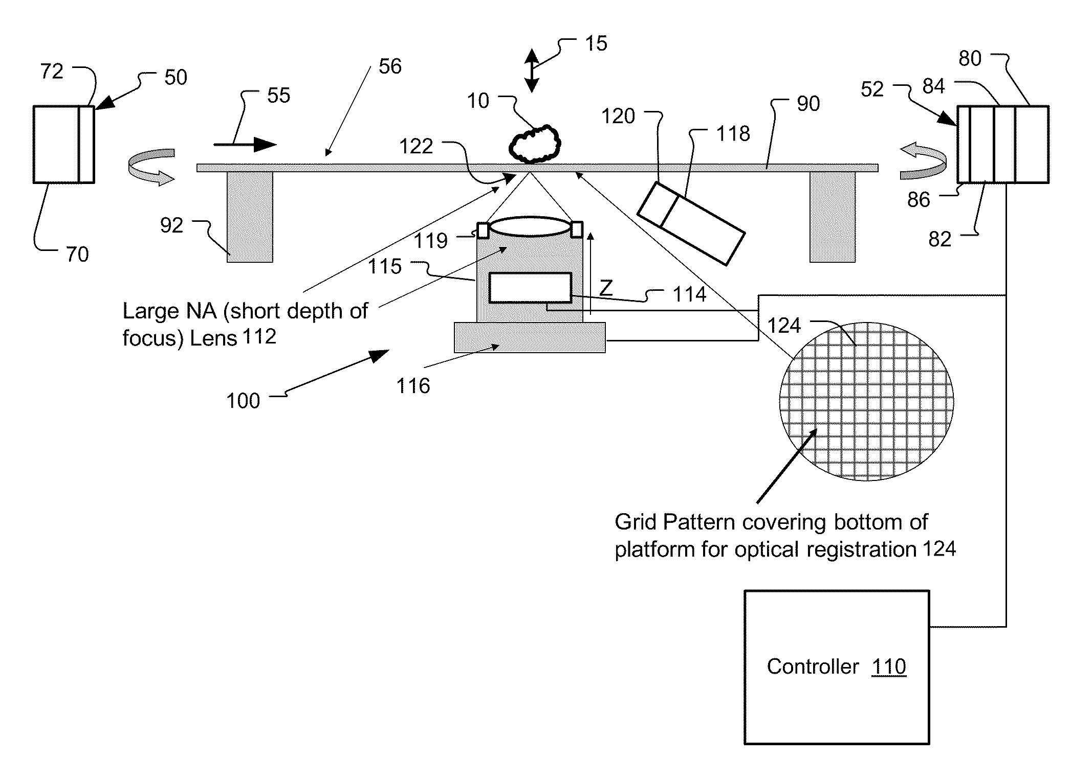
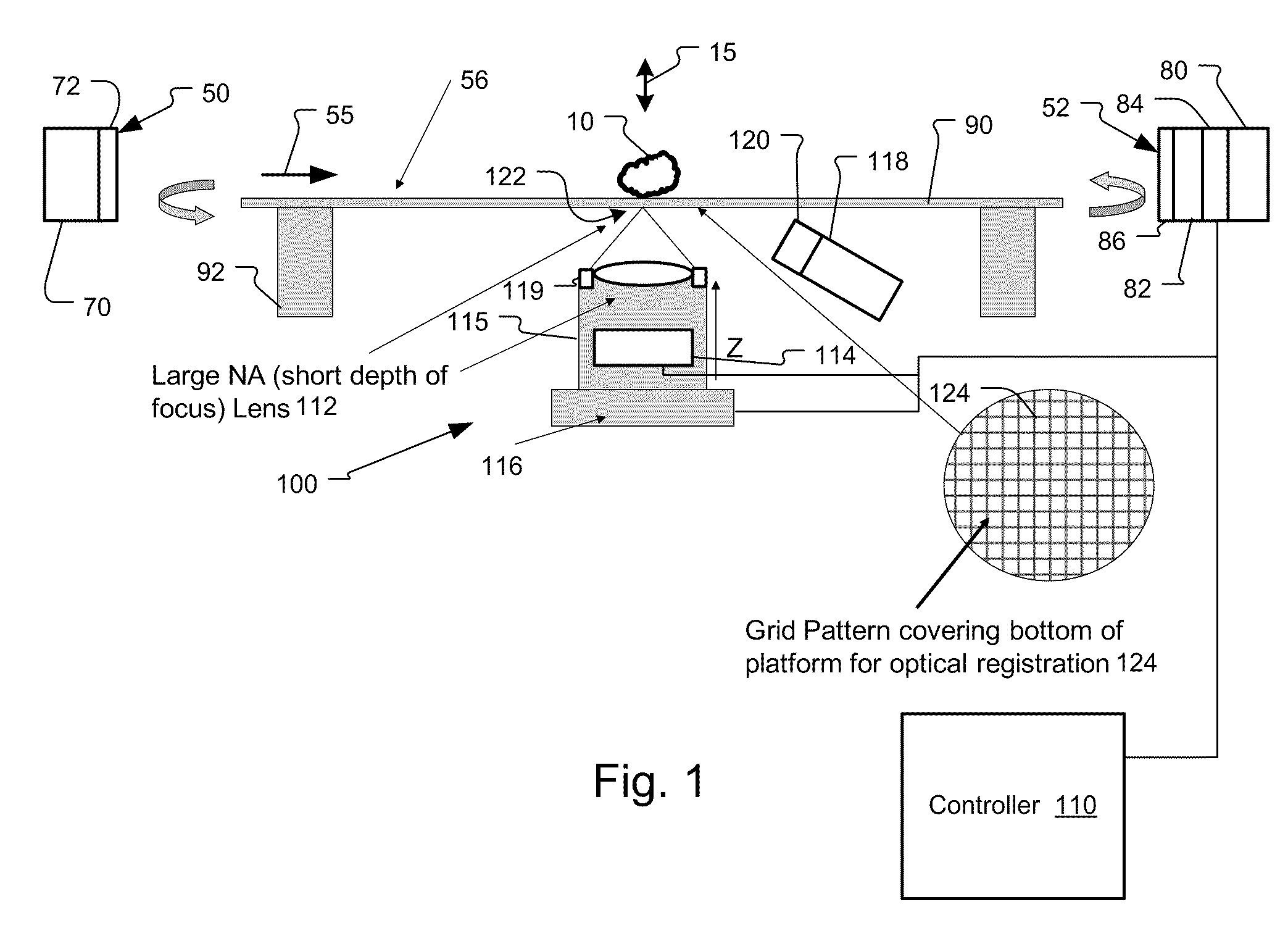
FIG. 1 shows an optical metrology system 100 integrated into a 3D imaging system 50, 52, 56 such as CT or laminography system that has been constructed according to the principles of the present invention.

In more detail, 3D imaging system comprises an X-ray source 50 and an X-ray detector 52 that acquire images laterally through the sample 10, at oblique angles through the sample 10 or vertically through the sample 10 depending on the configuration or application. The images detected by the detector 52 are provided to controller 110.

In one example, the X-ray source 50 a synchrotron beam line. In other examples, the source is a laboratory source 70 such as a microfocus source or rotating anode source. In implementations, the X-ray source 50 also includes a condenser 72 for concentrating the X-ray beam 55 on the sample 10.

The X-ray detector 52 in one implementation comprises a charge-coupled device (CCD) or CMOS chip 80 having a two dimensional array of pixels, of at least 1,024×1,024...


PUM


Abstract

A metrology system that uses an imaging system to monitor alignment features on the sample or sample holder of an X-ray laminography or tomography system. the metrology system has the capability to provide both sample shift and sample rotation movement data to a data acquisition system. These shift and rotation data can be used in alignment routines to produce 3D reconstructions from the X-ray images/projections. The metrology system is based on an imaging and focusing measurement of intrinsic feature of the sample or artificial features fabricated on the sample or sample holder.

Description

BACKGROUND OF THE INVENTIONComputed tomography (CT) and laminography systems are able to image three dimensional (3D) structures of samples, particularly their embedded structures and often without any destructive or invasive process. These techniques have found a wide range of applications from non-destructive integrated circuit testing to medical / biological imaging. In these systems, a series of projection images are acquired at different view angles to gain different perspectives of the specimen. These projections are then mathematically assembled to reconstruct a 3D image that represents the 3D structure of the specimen. X-ray radiation is typically used in these applications as it provides a good combination of high penetration, low scattering, and relatively simple absorption characteristics.A key requirement in producing the 3D images in both CT and laminography systems is that all projections must be aligned so that the sample appears to rotate through a common rotation axis...

Claims


Application Information

Patent Timeline
IPC IPC(8): G01N23/04
CPCG01N23/046G01N2223/419G01N23/044
Inventor CASE, THOMAS A.YUN, WENBINGLYON, ALAN FRANCIS
Owner CARL ZEISS X RAY MICROSCOPY
Why Eureka
Try Eureka