Single transfer insert placement method and apparatus

a single transfer insert and placement method technology, applied in mechanical devices, transportation and packaging, manufacturing tools, etc., can solve problems such as excessive wear on devices

Active Publication Date: 2011-07-12
CURT G JOA
View PDF483 Cites 81 Cited by
  • Summary
  • Abstract
  • Description
  • Claims
  • Application Information

AI Technical Summary

Problems solved by technology

Therefore, it is desirable to compensate for the difference between the cut pitch, X, and the receive pitch, Y. Re-pitching is known in the art, but prior art device techniques tend to cause excessive wear on the devices due to the momentum changes that are required.

Method used


Image

  • Single transfer insert placement method and apparatus
  • Single transfer insert placement method and apparatus
  • Single transfer insert placement method and apparatus

Examples


Embodiment Construction

[0051]Although the disclosure hereof is detailed and exact to enable those skilled in the art to practice the invention, the physical embodiments herein disclosed merely exemplify the invention, which may be embodied in other specific structures. While the preferred embodiment has been described, the details may be changed without departing from the invention, which is defined by the claims.

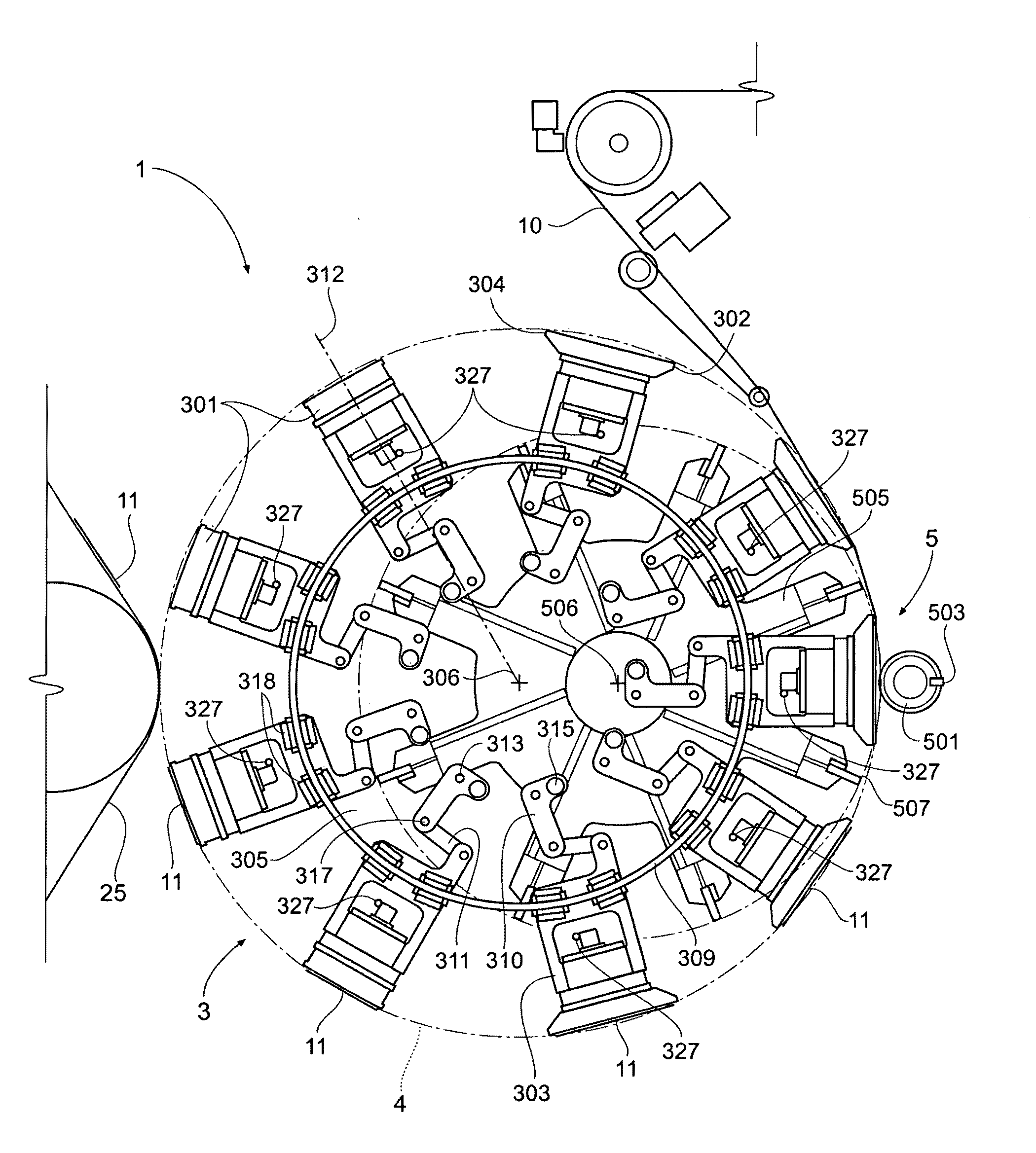
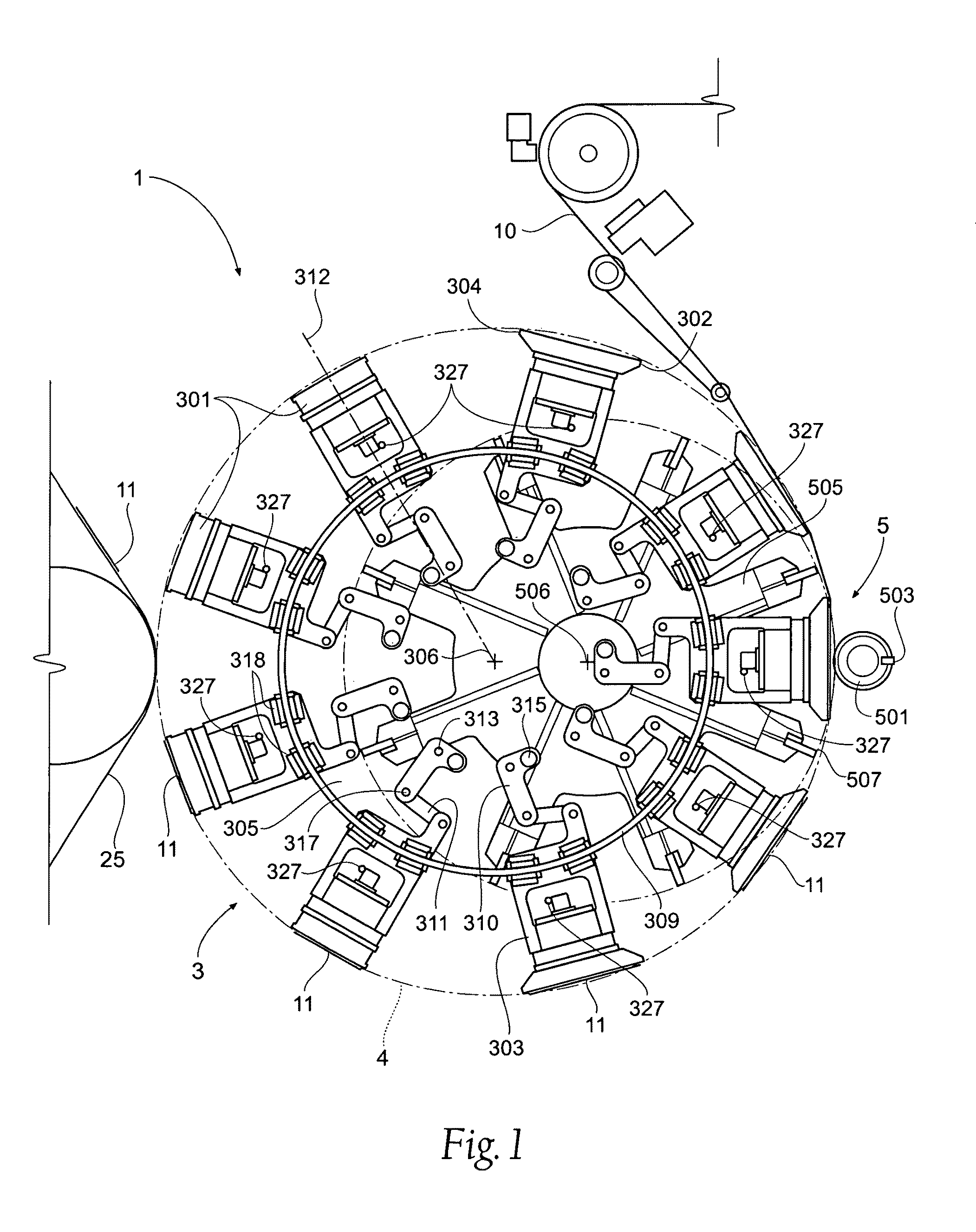
[0052]Turning now to the drawings, FIG. 1 illustrates a front elevation view of a first embodiment 1 of an apparatus according to the present invention. The apparatus 1 preferably includes a transfer mechanism 3 and a cutter 5.

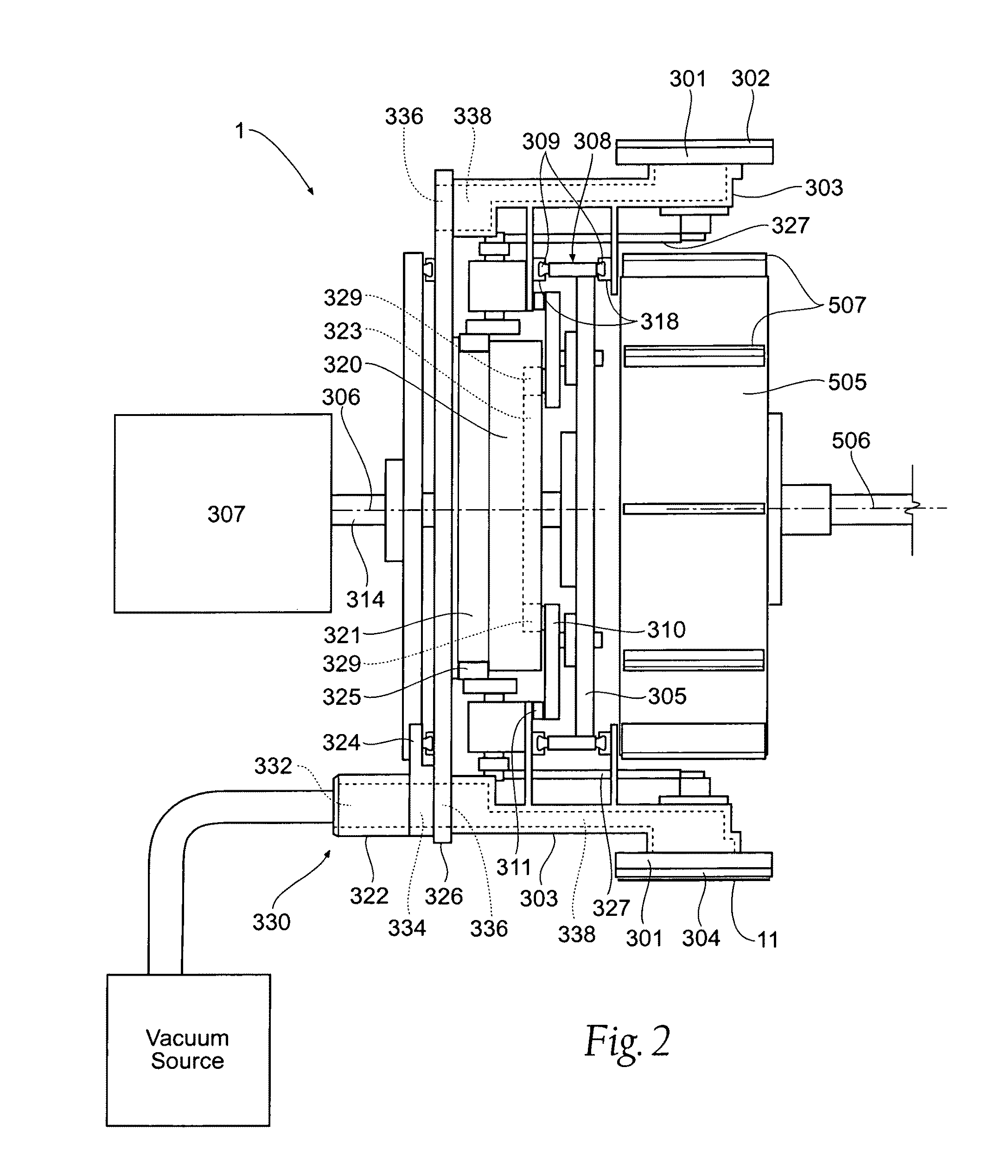
[0053]Referring, in addition to FIG. 1, to FIGS. 2 and 3, the transfer mechanism 3 includes a plurality of pucks 301. Each puck 301 has a leading edge 302 and a trailing edge 304 and is coupled to a puck support 303, which is ultimately rotated by a puck wheel 305 about a puck transfer axis 306, which is a major axis of rotation, through a transfer path 4. As used throughou...


PUM

PropertyMeasurementUnit
spin angleaaaaaaaaaa
angleaaaaaaaaaa
vacuum interfaceaaaaaaaaaa

Abstract

An apparatus and method is provided for single transfer insert placement. The apparatus receives continuous web material and cuts a discrete section or pad from the web. The pad is then supported on a single transfer surface. The single transfer surface then may spin the supported pad to a desired angle and provide the pad to a receiving surface at a desired interval.

Description

RELATED APPLICATIONS[0001]This application claims the benefit of U.S. Provisional Patent Application Ser. No. 60 / 902,477, filed 21 Feb. 2007, and entitled “Single Transfer Insert Placement Method and Apparatus.”BACKGROUND OF THE INVENTION[0002]This invention relates to a method and apparatus for receiving and cutting a continuous web, and transferring articles, or inserts, such as absorbent pads cut from the web in the manufacture of disposable absorbent articles such as diapers, incontinence control garments or female sanitary pads as they advance along a production line.[0003]In the production and manufacture of disposable products such as sanitary napkins or pants-type diapers, it frequently becomes necessary to manufacture a component of the product in one orientation, and then to spin that component part to a predetermined angle, which is suitably oriented for use in another step in the production process. Various devices have been developed for this purpose and are known to th...

Claims


Application Information

Patent Timeline
Patent Type & Authority Patents(United States)
IPC IPC(8): B26D1/40
CPCA61F13/15723A61F13/15764B26D1/425B26D7/018B65H35/08F16H53/06B65H39/14B65H2301/33216B65H2406/3452B65H2406/3612B65H2801/57Y10T83/21Y10T83/207Y10T83/0448Y10T83/483Y10T83/6667Y10T83/2196Y10T83/494Y10T83/2185Y10T83/2066Y10T83/219Y10T83/0515Y10T83/8739
Inventor MCCABE, JOHN A.
Owner CURT G JOA
Why Eureka
Try Eureka