Delivery system with variable delivery rate for deploying a medical device

a delivery system and medical device technology, applied in the field of medical device delivery systems and methods, can solve the problems of long stents that often require additional deployment time, and the delivery system usually requires a slower and more controlled deployment rate, so as to achieve fast transformation, high torque, and the effect of rapid deploymen

a delivery system and medical device technology, applied in the field of medical device delivery systems and methods, can solve the problems of long stents that often require additional deployment time, and the delivery system usually requires a slower and more controlled deployment rate, so as to achieve fast transformation, high torque, and the effect of rapid deploymen

US7976574B2Inactive Publication Date: 2011-07-12ABBOTT CARDIOVASCULAR

Image

  • Delivery system with variable delivery rate for deploying a medical device
  • Delivery system with variable delivery rate for deploying a medical device
  • Delivery system with variable delivery rate for deploying a medical device

Examples


Embodiment Construction

[0041]The present invention relates to a system that delivers and deploys a medical device at a target site within a patient's body, such as a body lumen. For illustration purposes, the following exemplary embodiments are directed to a system for delivering and deploying a self-expanding stent, although it is understood that the present invention is applicable to other medical devices which are implantable in a body lumen as well as other parts of the body. Additionally, the medical device can be either self-expanding or a non self-expanding (balloon expandable). If the stent is balloon expandable, then a balloon catheter would be used to expand the stent at the target location.

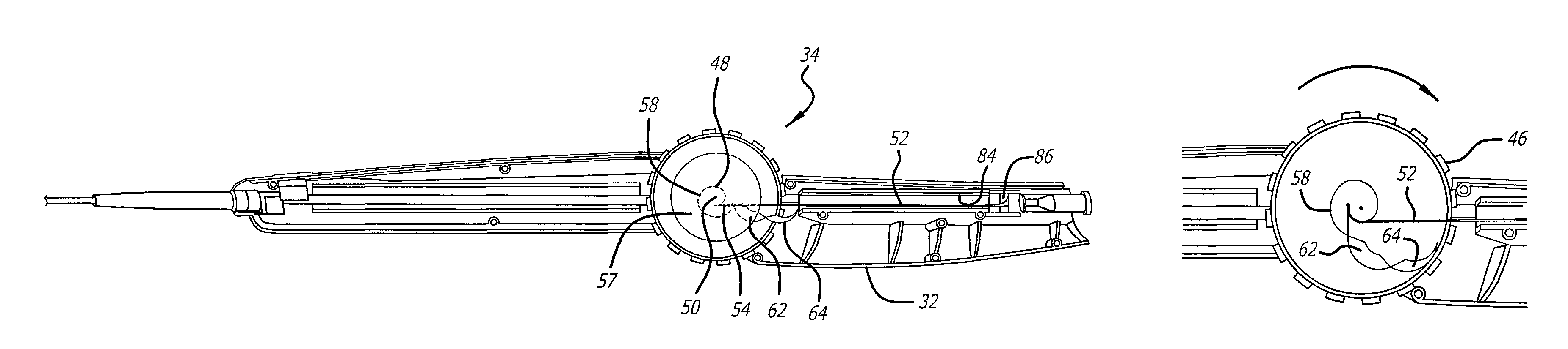
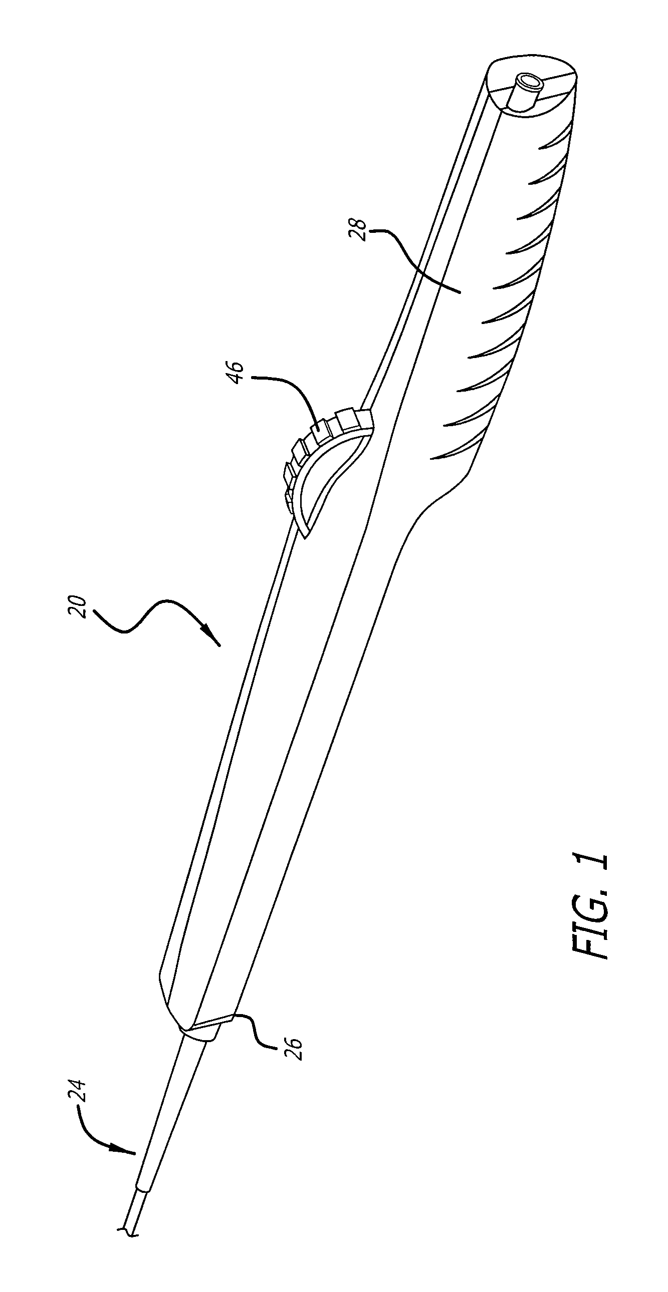
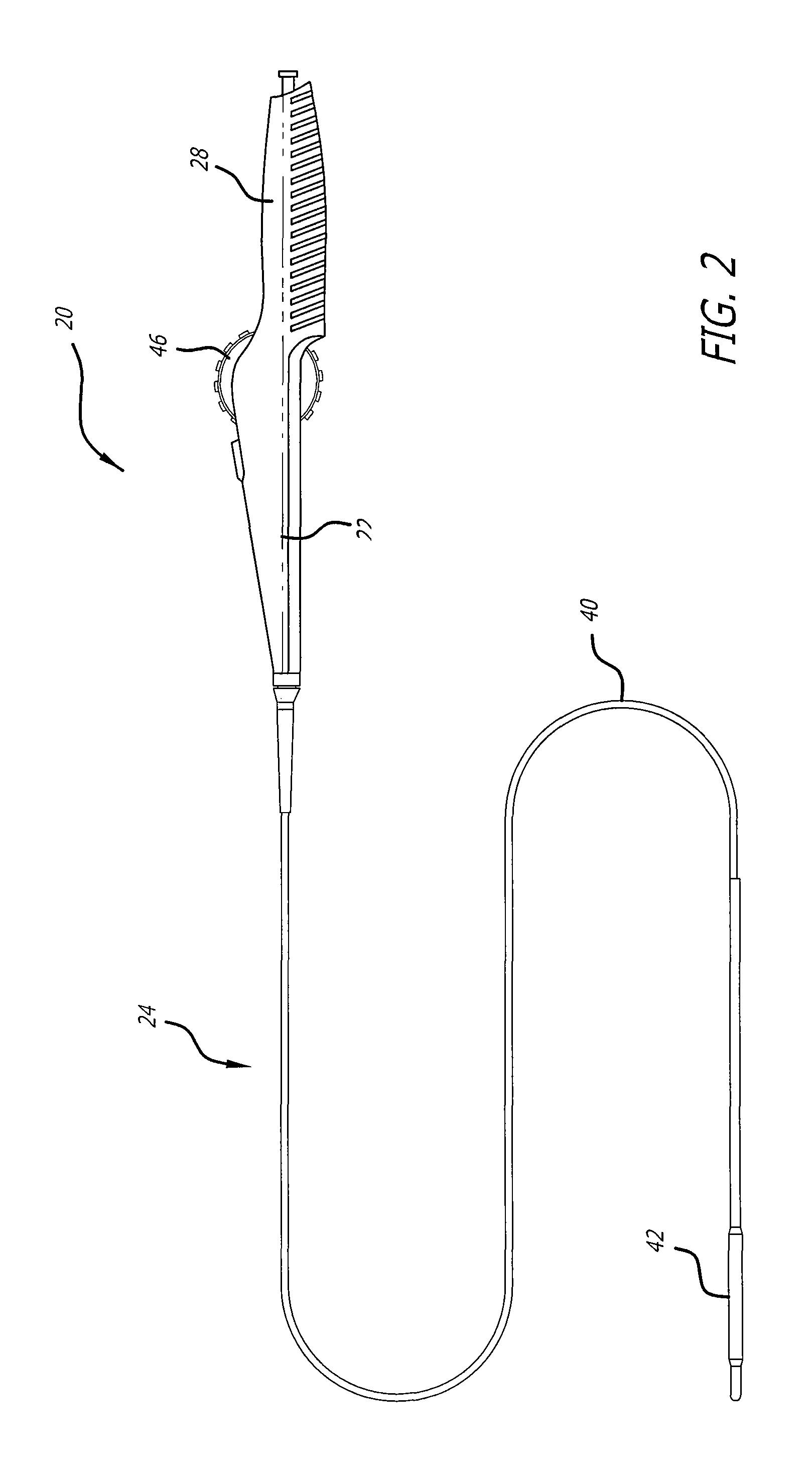
[0042]Referring now to FIGS. 1-6, a delivery system 20 with a handle assembly 22 embodying features of the present invention is illustrated. The delivery system includes a catheter portion 24 coupled to the distal end 26 of the handle assembly 22. The handle assembly 22 is generally elongate and includes a gr...


PUM


Abstract

A delivery system utilizes a handle assembly including an actuating mechanism capable of initially providing sufficient mechanical advantage to overcome static friction when initiating deployment of the medical device. The actuating mechanism includes components which help to increase the speed of deployment as the physician continues to manipulate the actuating mechanism.

Description

BACKGROUND[0001]The present invention relates generally to delivery systems and methods for deploying medical devices and, more particularly, to delivery systems and methods for their use to accurately deploy medical devices, such as a stent, a vascular stent-graft and the like, in a body vessel of a patient for the treatment of stenosis, aortic aneurysms and other afflictions which may strike body vessels. The present invention also can be used to deliver medical devices for arthroscopic surgery and other surgical procedures.[0002]Stents are generally cylindrically shaped devices which function to hold open and sometimes expand a segment of a blood vessel or other arterial lumen, such as coronary artery. Stents are usually delivered in a compressed condition to the target site and then deployed at that location into an expanded condition to support the vessel and help maintain it in an open position. They are particularly suitable for use to support and hold back a dissected arteri...

Claims


Application Information

Patent Timeline
12 Jul 2011
Publication
US7976574B2
IPC
A61F2/06
CPC
A61F2/95; A61F2/966; A61F2002/9517; A61F2/9517
Inventors
PAPP, JOHN E.