
Imaging interferometric microscopy

a technology of interferometry and microscope, which is applied in the field of imaging interferometry microscope, can solve the problems of restricted resolution of traditional microscopy approaches

Active Publication Date: 2011-07-12
STC UNM
View PDF1 Cites 10 Cited by
  • Summary
  • Abstract
  • Description
  • Claims
  • Application Information

AI Technical Summary

Benefits of technology

The present patent teaches a method and apparatus for microscopy that uses multiple illumination beams with different angles to capture sub-images of an object. These sub-images are then combined to create a composite image that includes information from all spatial frequency regions. The method and apparatus can enhance the sub-images using signal processing algorithms to improve image quality. The technical effects of this invention include improved image quality, improved spatial frequency coverage, and reduced aberrations.

Problems solved by technology

Traditional microscopy approaches are restricted in resolution by the low-pass filter characteristics of the optical system.

Method used


Image

  • Imaging interferometric microscopy
  • Imaging interferometric microscopy
  • Imaging interferometric microscopy

Examples


Embodiment Construction

[0023]Reference will now be made in detail to the present embodiments (exemplary embodiments) of the invention, examples of which are illustrated in the accompanying drawings. Wherever possible, the same reference numbers will be used throughout the drawings to refer to the same or like parts. In the following description, reference is made to the accompanying drawings that form a part thereof, and in which is shown by way of illustration specific exemplary embodiments in which the invention may be practiced. These embodiments are described in sufficient detail to enable those skilled in the art to practice the invention and it is to be understood that other embodiments may be utilized and that changes may be made without departing from the scope of the invention. The following description is, therefore, merely exemplary.

[0024]While the invention has been illustrated with respect to one or more implementations, alterations and / or modifications can be made to the illustrated examples...


PUM


Abstract

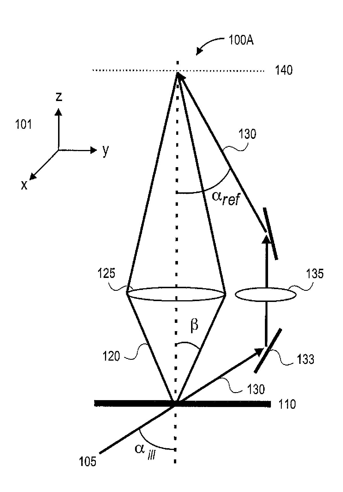
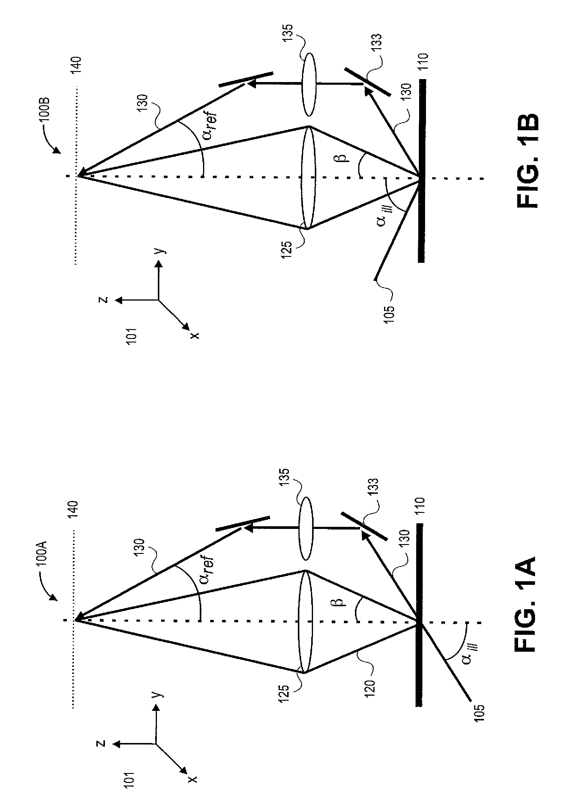
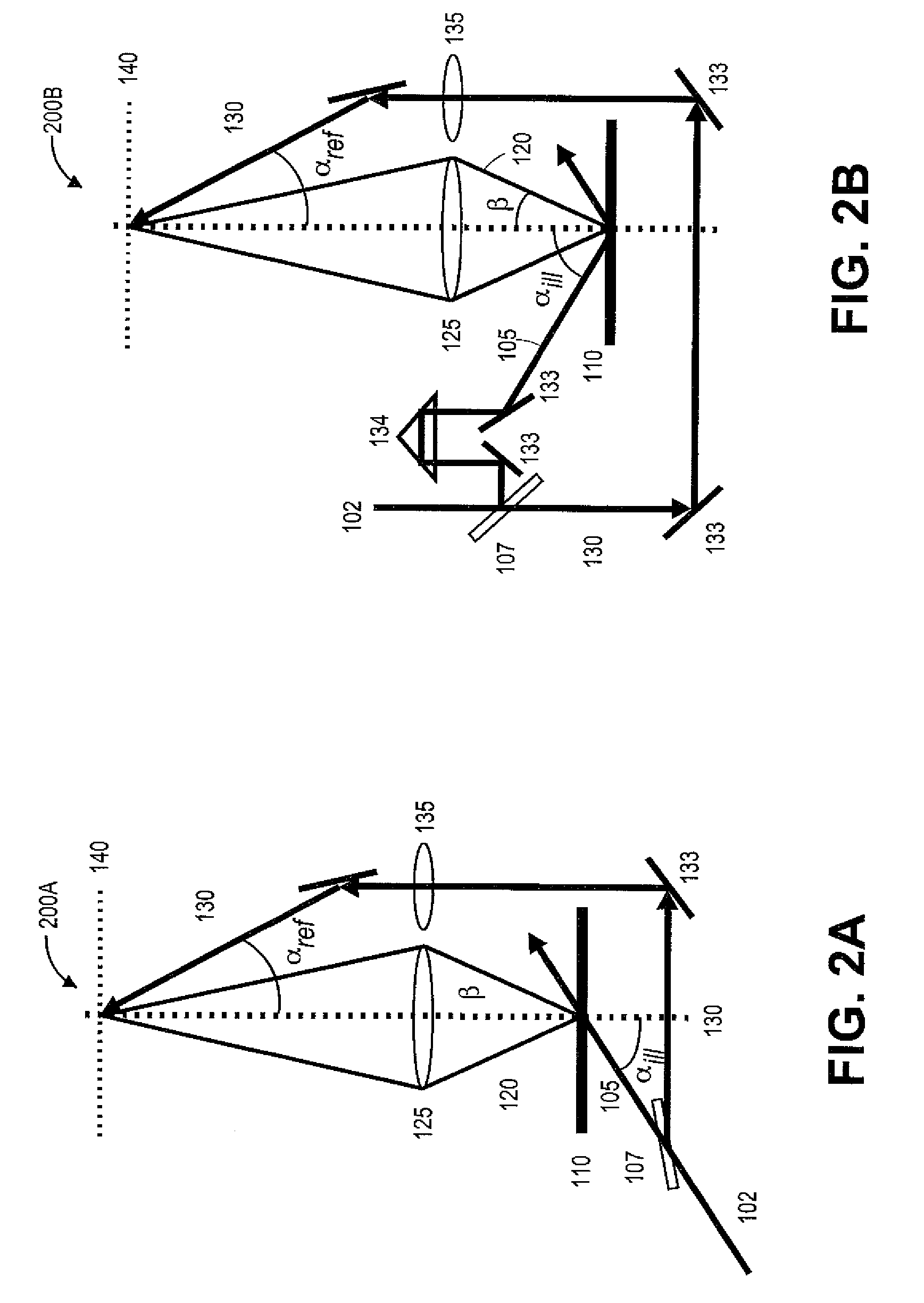
Exemplary embodiments provide an image interferometric microscope (IIM) and methods for image interferometric microscopy. The disclosed IIM can approach the linear systems limits of optical resolution by using a plurality of off-axis illuminations to access high spatial frequencies along with interferometric reintroduction of a zero-order reference beam on the low-NA side of the optical system. In some embodiments, a thin object can be placed normal to the optical axis and the frequency space limit can be extended to about [(1+NA)n / λ], where NA is the numerical-aperture of the objective lens used, n is the refraction index of the transmission medium and λ is an optical wavelength. In other embodiments, tilting the object plane can further allow collection of diffraction information up to the material transmission bandpass limited spatial frequency of about 2n / λ.

Description

RELATED APPLICATIONS[0001]This application claims priority from U.S. Provisional Patent Application Ser. No. 60 / 917,170, filed May 10, 2007, which is hereby incorporated by reference in its entirety.GOVERNMENT INTEREST[0002]This invention was made with U.S. Government support under Contract No. HR0011-05-1-0006 awarded by the Defense Advanced Research Projects Agency. As a result, the U.S. Government has certain rights in this invention.FIELD OF THE INVENTION[0003]This invention relates generally to an imaging interferometric microscopy, and, more particularly, to an imaging interferometric microscope and methods for providing an optical resolution approaching the linear systems limits of the transmission medium extending to 2n / λ where n is the medium refractive index and λ is an optical wavelength.BACKGROUND OF THE INVENTION[0004]Microscopy is among the oldest applications of optical science and remains one of the most widely used optical technologies. In spite of impressive result...

Claims


Application Information

Patent Timeline
Patent Type & Authority Patents(United States)
IPC IPC(8): G02B21/00
CPCG02B21/18G02B21/367G02B21/06
Inventor BRUECK, STEVEN R. J.NEUMANN, ALEXANDERKUZNETSOVA, YULIYA V.
Owner STC UNM
Learn More