
Wind turbine generator rotor, wind turbine generator and wind turbine generator system

a wind turbine generator and wind turbine technology, applied in the field of wind turbine generators, can solve the problems of increasing construction costs, increasing the risk of lighting, and increasing the noise of propeller wind turbines, and achieve the effect of easy rotation

Active Publication Date: 2011-07-19
AKAMINE TATUMI
View PDF20 Cites 7 Cited by
  • Summary
  • Abstract
  • Description
  • Claims
  • Application Information

AI Technical Summary

Benefits of technology

The system enables cost-effective, efficient power generation from weak winds, reduces construction and maintenance costs, and enhances safety by minimizing the risk of blade breakage and lightning strikes, while allowing for remote installation and operation with minimal human intervention.

Problems solved by technology

However, wind turbines of this type have the following disadvantages.
A propeller wind turbine has a restriction that a support column for supporting the propeller needs to be strengthened rather than the propeller itself, which leads to an increase in construction cost.
Moreover, since propeller wind turbines are constructed in a large site, they are more likely to be hit by lighting.
Furthermore, propeller wind turbines make large wind noise since the blades constituting the propeller are made of metal or hard plastic.
In addition, when the blades are hit by a gust of strong wind, they might break into pieces, and the scattered pieces might hurt humans and animals.
Hence, there is also a location problem that propeller wind turbines need to be constructed in a large and remote site.
However, disadvantageously, such blades might not rotate depending on the wind direction.

Method used


Image

  • Wind turbine generator rotor, wind turbine generator and wind turbine generator system
  • Wind turbine generator rotor, wind turbine generator and wind turbine generator system
  • Wind turbine generator rotor, wind turbine generator and wind turbine generator system

Examples


Embodiment Construction

[0118]Detailed description will be given below of the present invention on the basis of the drawings. However, the scope of the present invention is not limited to the description.

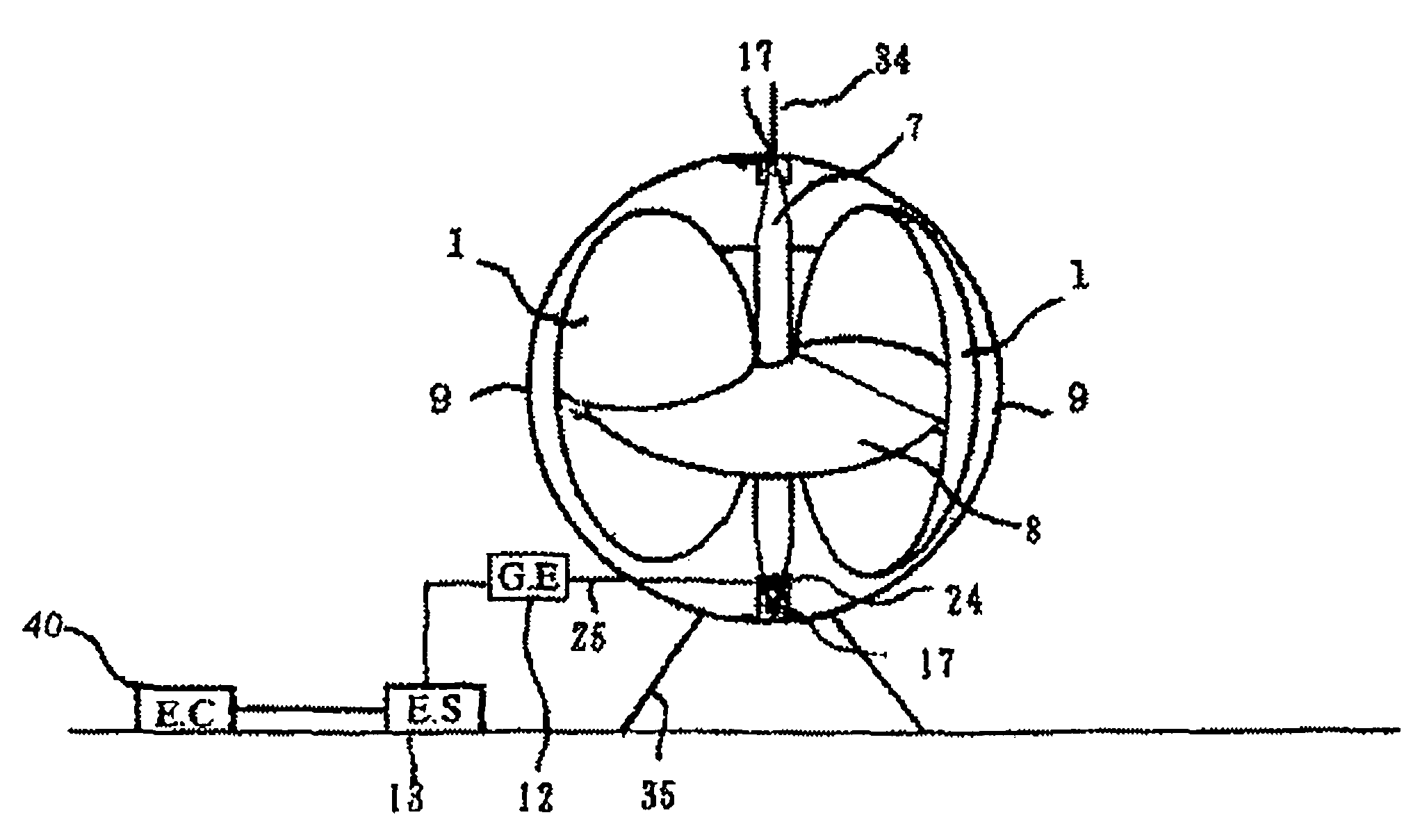
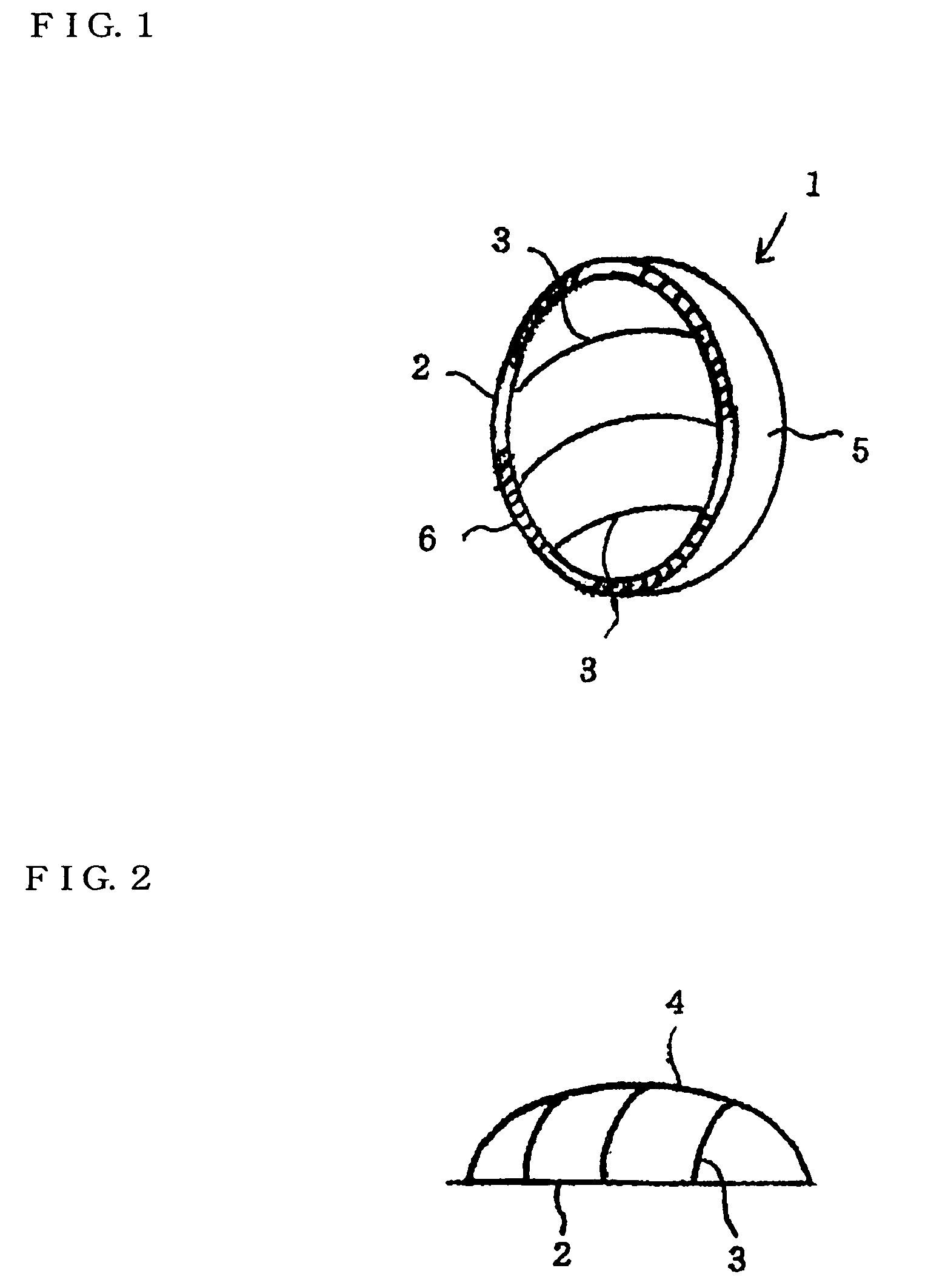
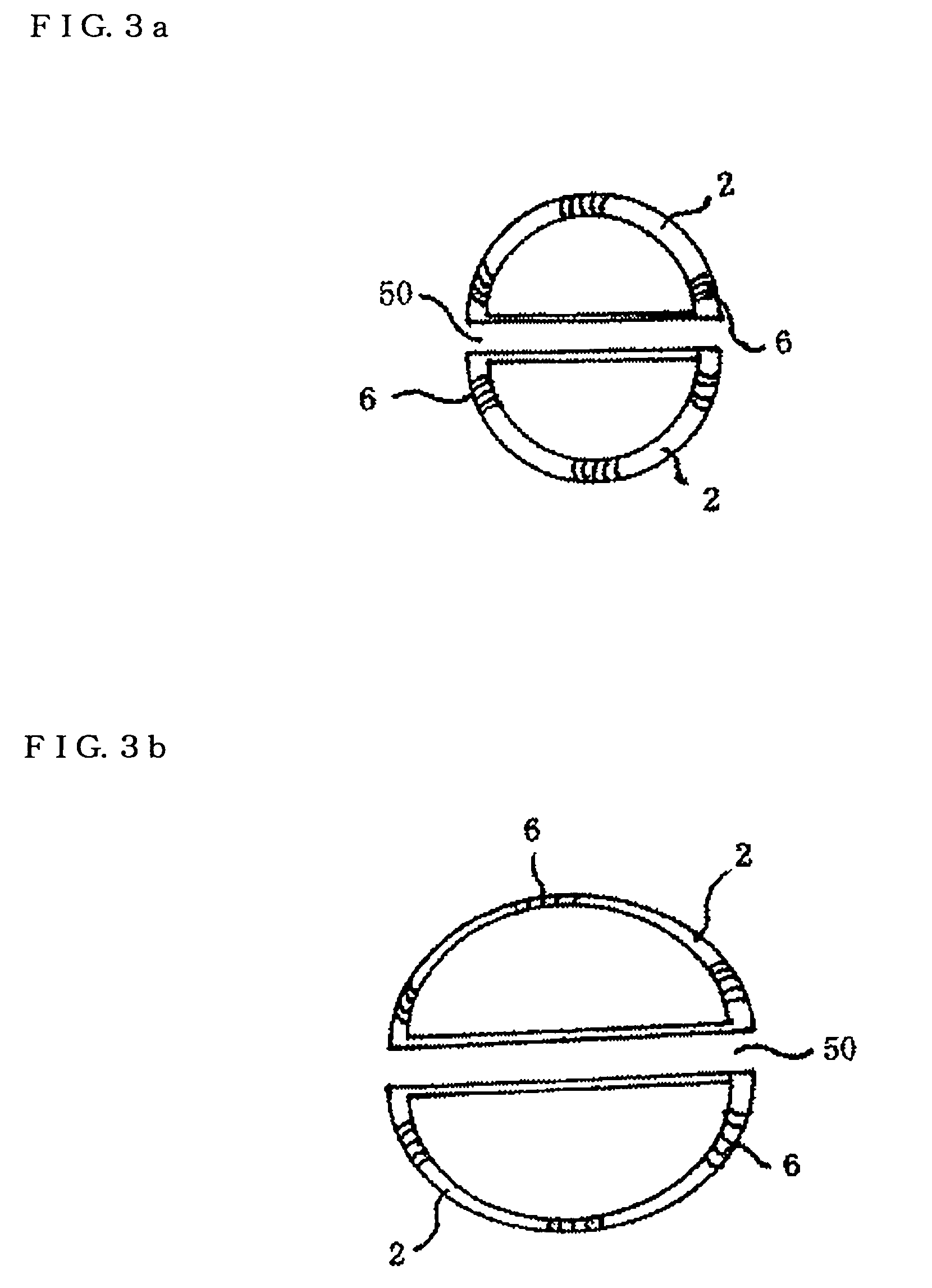
[0119]FIG. 1 shows a basic shape of a rotor blade 1 used in a wind turbine generator of the present invention, and FIG. 2 is an illustration showing a structure of a frame unit shown in FIG. 1. FIG. 3 is illustrations showing variations of a frame 2, and shapes for allowing a flywheel 8 to be sandwiched and fitted to a slot 50 (as shown in FIG. 7 or FIG. 8) are shown in FIGS. 3a and 3b, respectively.

[0120]The rotor blade 1 includes a frame unit 10. As shown in FIG. 1 and FIG. 2, the frame unit 10 includes: the frame 2 having openings in a semicircular shape or a semielliptical shape, or a different shape such as a leaf shape or a comb shape; multiple first support frames 3 each provided in an extending manner from the frame 2 so as to form a semielliptical shape; and a central support frame 4 supporting th...


PUM


Abstract

Provided is a wind power generating apparatus adopts a rotor blade including a frame body unit composed of a frame body having an opening and a plurality of support frames extending from the frame body, and a sail portion adhered to cover the frame body unit. The frame body unit is configured to be retractable using wires and a servo-motor to decrease the surface area of the rotor blade in high winds. As a result, the rotor blade can rotate easily with a low wind power and can rotate continuously with an inertial power, once it starts the rotations, so that it can run the power generating function at a set value of a rated speed of rotations of 700 to 2,000 rpm.

Description

BACKGROUND OF THE INVENTION[0001]1. Technical Field[0002]The present invention relates to a wind turbine generator, more specifically, a wind turbine generator that includes a support column and a rotor with multiple canvas blades attached to the support column, the support column detachably fixed to an inner part of a circular ring and provided with tapered end portions, and that can be rotated by even weak wind force and can also be rotated continuously by inertial force after the rotation.[0003]2. Background Art[0004]In conventional wind power generation, propeller wind turbines and Darrieus wind turbines are the mainstreams of the horizontal axis wind turbines and the vertical axis wind turbines, respectively. However, it is said that these types of wind turbines can only deliver their performance with a wind speed of 10 m / s or faster.[0005]Especially in wind power generation using propeller wind turbines, it has been inevitable that the entire wind turbine results in being larg...

Claims


Application Information

Patent Timeline
Patent Type & Authority Patents(United States)
IPC IPC(8): F03D3/00
CPCF03D3/061F03D3/062F03D11/04F05B2240/216F05B2240/313F05B2250/241Y02E10/728Y02E10/74F03D13/20F03D15/10F03D9/11F03D9/25Y02E70/30
Inventor AKAMINE, TATUMI
Owner AKAMINE TATUMI
Learn More