Highly accurate temperature stable clock based on differential frequency discrimination of oscillators

a temperature stable clock and oscillator technology, applied in the field of precision timing, can solve the problems of difficult use of compensation techniques developed for quartz crystal oscillators, inability to apply the approach in the context of mems oscillators, and complex process used to fabricate such devices

Inactive Publication Date: 2011-07-19
SILICON LAB INC
View PDF4 Cites 29 Cited by
  • Summary
  • Abstract
  • Description
  • Claims
  • Application Information

AI Technical Summary

Problems solved by technology

Furthermore, consistency requirements for the performance of MEMS devices (both intra-device and device-two-device) often dictate that the processes used to fabricate such MEMS devices need to be extremely sophisticated.
This makes the use of compensation techniques developed for quartz crystal oscillators very difficult, where a typical AT-cut first mode resonator experiences a maximum excursion of + / −20 ppm over the full temperature range.
However, this approach is not used in the context of MEMS oscillators.
Also, since uncompensated quartz oscillators have a lower temperature coefficient than MEMS oscillators, these conventional approaches are not used in a wide range of temperatures for temperature compensations of the oscillator.
Furthermore, traditional electrostatic pulling is not effective in high-frequency MEMS oscillators.
In MEMS oscillators, capacitive pulling, like used in quartz-based oscillators, may also not be effective to adjust the output frequency for both initial accuracy and temperature stability due to extremely small effective capacitance of the MEMS resonators.

Method used


Image

  • Highly accurate temperature stable clock based on differential frequency discrimination of oscillators
  • Highly accurate temperature stable clock based on differential frequency discrimination of oscillators
  • Highly accurate temperature stable clock based on differential frequency discrimination of oscillators

Examples


Embodiment Construction

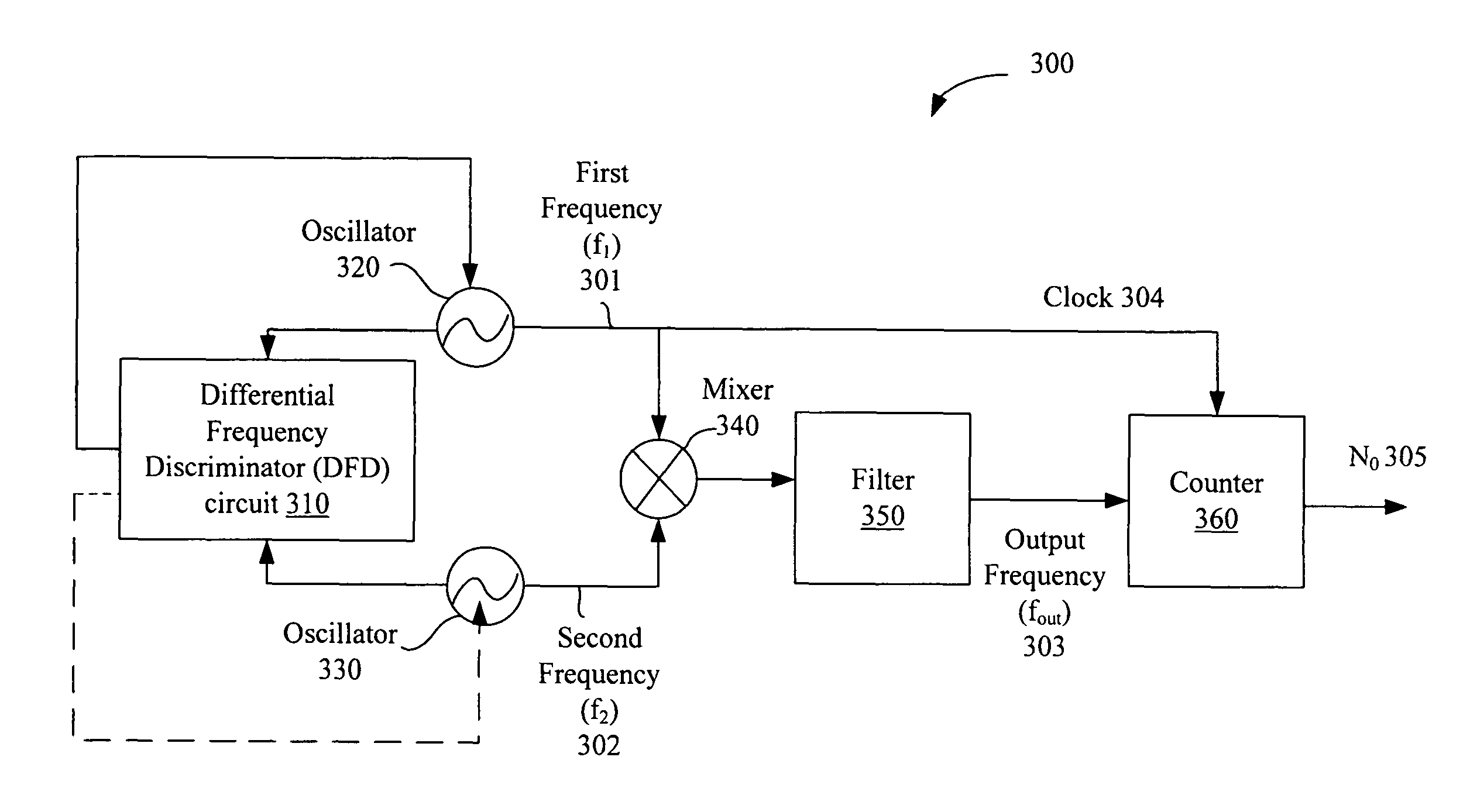
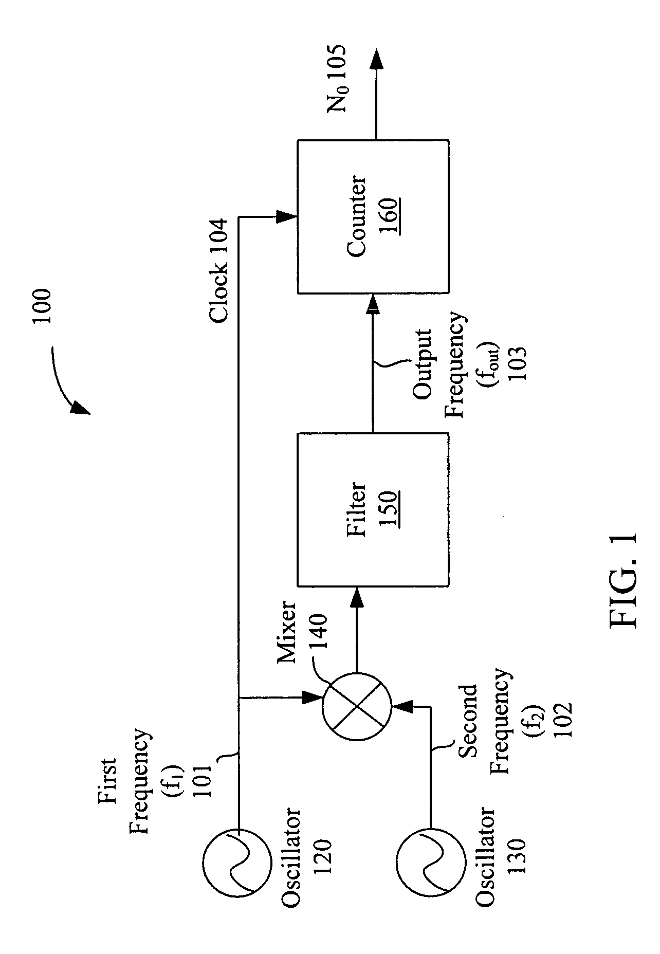
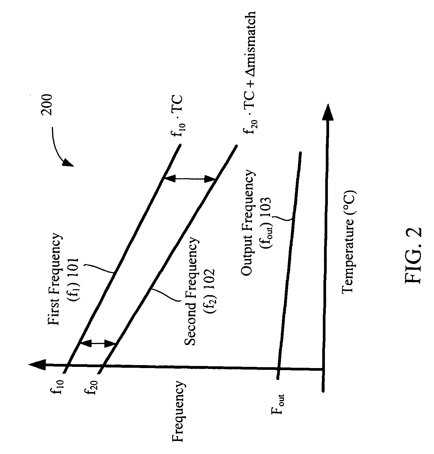
[0018]Disclosed herein is a differential frequency discriminator. In particular, the embodiments described herein are directed to apparatuses and methods for compensating for a mismatch in temperature coefficients of two oscillator frequencies to match a desired frequency ratio between the two oscillator frequencies over a temperature range. In one embodiment of a temperature sensor, first and second oscillators of different temperature characteristics are coupled to a differential frequency discriminator (DFD) circuit. The DFD circuit compensates for the different characteristics in order to match a frequency difference between the first and second frequencies over a temperature range.

[0019]In the following description, for purposes of explanation, numerous specific details are set forth, such as material compositions and chemical regimes, in order to provide a thorough understanding of the invention. It should be apparent to one skilled in the art that the present invention may be...


PUM


Abstract

An apparatus and a method for compensating for a mismatch in temperature coefficients of two oscillator frequencies to match a desired frequency ratio between the two oscillator frequencies over a temperature range. In one embodiment of a temperature sensor, first and second oscillators of different temperature characteristics are coupled to a differential frequency discriminator (DFD) circuit. The DFD circuit compensates for the different characteristics in order to match a frequency difference between the first and second frequencies over a temperature range.

Description

TECHNICAL FIELD[0001]Embodiments of the invention relate to the field of precision timing; and more specifically, to oscillator-based precision timing applications.BACKGROUND[0002]A resonator is a device or system that exhibits resonance or resonant behavior, that is, it naturally oscillates at some frequencies, called its resonance frequencies, with greater amplitude than at others. Resonators can be, for example, crystal oscillators (also known as quartz oscillators), inductance-capacitive (LC) oscillators, resistance-capacitive (RC) oscillators, and Microelectromechanical systems (MEMS) oscillators, also referred to as micromechanical MEMS oscillators. A crystal oscillator is an electronic circuit that uses the mechanical resonance of a vibrating crystal of piezoelectric material to create an electrical signal with a very precise frequency. Crystal oscillators, such as quartz oscillators, are commonly used to generate frequencies to keep track of time (as in quartz clocks) or to ...

Claims


Application Information

Patent Timeline
Patent Type & Authority Patents(United States)
IPC IPC(8): H03B5/32
CPCH03L1/022H03L7/16H03L7/085
Inventor QUEVY, EMMANUEL P.SETH, MANU
Owner SILICON LAB INC
Why Eureka
Try Eureka