Method and apparatus for data frame synchronization

a data frame and synchronization technology, applied in the field of data frame synchronization, can solve the problems of increasing processor utilization, complex and larger logic, increasing processor utilization,

Inactive Publication Date: 2011-07-19
MARVELL INT LTD
View PDF3 Cites 45 Cited by
  • Summary
  • Abstract
  • Description
  • Claims
  • Application Information

AI Technical Summary

Problems solved by technology

This creates more complex and larger logic, utilizing many thousands of gates within a chip, thereby making the chip more expensive.
Existing downstream frame synchronization schemes also ofte

Method used


Image

  • Method and apparatus for data frame synchronization
  • Method and apparatus for data frame synchronization
  • Method and apparatus for data frame synchronization

Examples


Embodiment Construction

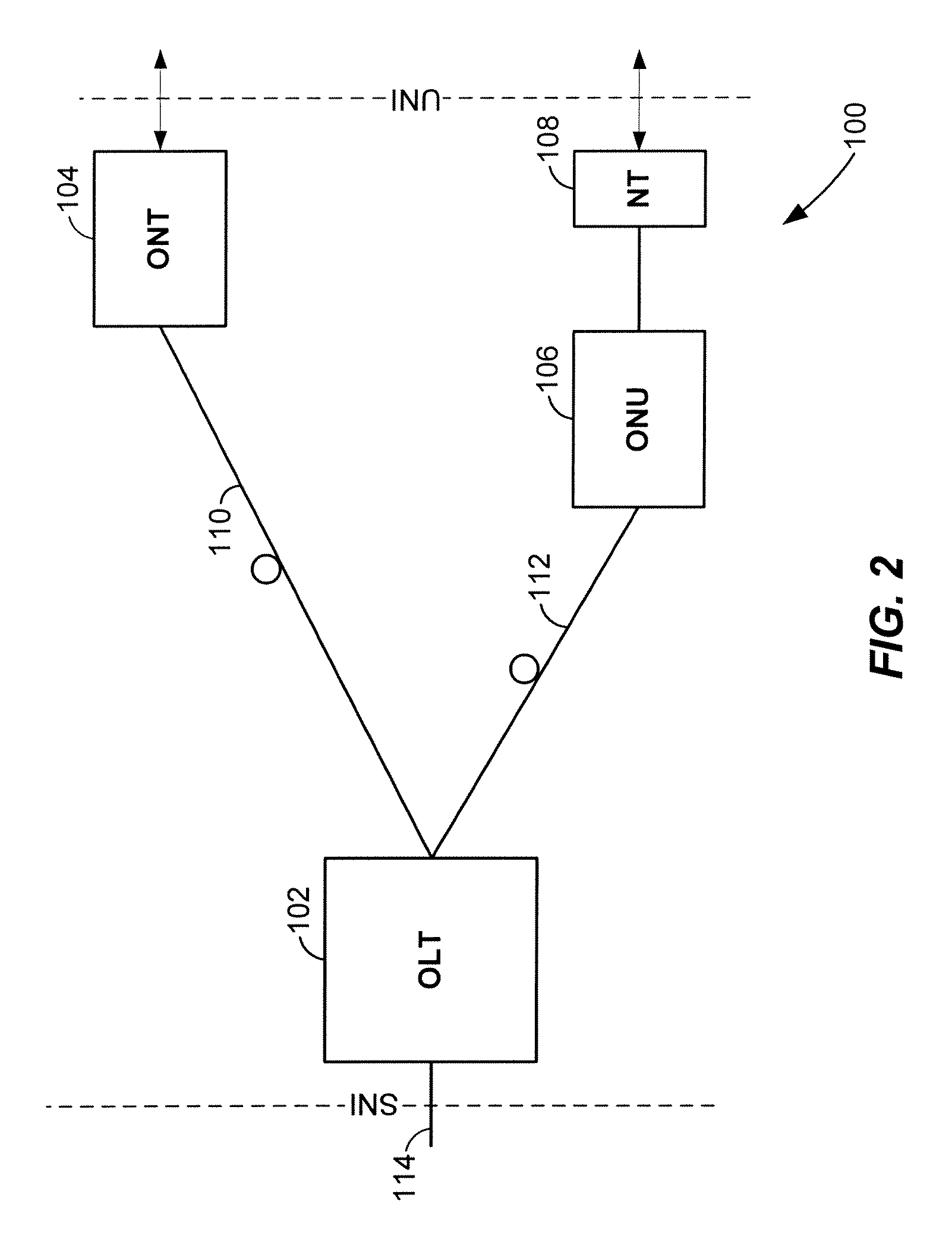
[0018]FIG. 2 is a block diagram of an example passive optical network 100 that includes an optical line termination (OLT) 102 coupled to an optical network terminal (ONT) 104 and an optical network unit (ONU) 106. Generally, the passive optical network 100 is a point-to-multipoint network, where the OLT 102 is provided as a service node interface, for example at a server or service provider, such as a internet service provider, television service provider, telephony service provider or other provider of network services. The ONT 104 and / or ONU 106 are each provided as an user node interface, for example at or near an end user. While the OLT 102 may be provided at the service provider site, the OLT 102 may also be provided as one of several OLTs within a distributed network, where each OLT is associated with corresponding ONUs 106 and / or ONTs 104.

[0019]As shown in FIG. 2, the OLT 102 is communicatively coupled to the ONT 104 via an optical fiber 110, and communicatively coupled to th...


PUM


Abstract

A circuit to synchronize with a data transmission includes a comparator to read a set of data within a serialized data transmission, compare the set of data to a predetermined data pattern and output a comparison result. For a serialized data transmission, the comparator receives the serialized transmission and a shift register serially coupled to the comparator to hold the data pattern. A synchronization detector receives a comparison hit vector based on the comparison result from the comparator and aligns a boundary of a data frame according to the comparison hit vector if the comparison hit vector indicates a match between the data pattern in the set of data and the predetermined data pattern. For a deserialized data transmission, each stage of a multistage shift register read a set of data from the deserialized data transmission and selectively outputs the set of data to a comparator which compares each set to a predetermined data pattern and output a comparison result. A synchronization detector receives the comparison result from the comparator and aligns a boundary of a data frame according to the comparison result if the comparison result indicates a match between a data pattern sub-set within a combined data pattern and the predetermined data pattern, where the sets of deserialized data comprise the combined data pattern.

Description

CROSS-REFERENCES TO RELATED APPLICATIONS[0001]The present application claims the benefit of U.S. Provisional Application No. 60 / 867,512, entitled “GPON DOWNSTREAM FRAME SYNCHRONIZATION MODULE,” filed on Nov. 28, 2006, which is hereby incorporated by reference herein in its entirety.FIELD OF TECHNOLOGY[0002]The present disclosure relates generally to data frame synchronization, and more particularly, to downstream frame synchronization within a gigabit passive optical network.DESCRIPTION OF THE RELATED ART[0003]In point-to-multipoint networks, such as passive optical networks, the upstream and downstream transmissions are based on a transmission convergence frame format. The downstream frame includes a Physical Control Block downstream (PCBd) or overhead, and a payload which may include an asynchronous transfer mode (ATM) partition, and a gigabit passive optical network (GPON) encapsulation method (GEM) partition. The downstream frame provides the common time reference for the GPON, ...

Claims


Application Information

Patent Timeline
IPC IPC(8): H04J3/06H04L7/00H04B10/00
CPCH04J3/0608H04J3/1694H04L7/033H04Q11/0067H04Q2011/0083
Inventor JOHNSTON, CESAR A.CHIANG, JOHN M.
Owner MARVELL INT LTD
Why Eureka
Try Eureka