Method for manufacturing long force sensors using screen printing technology

a technology of screen printing and sensors, applied in the field of manufacturing long force sensors, can solve the problems of screen printing technology tolerance errors, unacceptable increase in resistance, etc., and achieve the effects of reducing width and separation, preventing bubbling and separation of sensors, and dramatically minimizing the dead area of sensors

Inactive Publication Date: 2011-07-26
ROSENBERG ILYA D +2
View PDF63 Cites 41 Cited by
  • Summary
  • Abstract
  • Description
  • Claims
  • Application Information

AI Technical Summary

Benefits of technology

It should be noted that sensors made as long as 60′ still require one to address the effect of thermal expansion and contraction, because of the difference in the coefficients of thermal expansion for plastic (as a part of the sensor) and asphalt or concrete (on or within which the sensor resides). In order to prevent bubbling and separation of the sensor from the ground, one may use a double sided adhesive, contact cement, epoxy or other adhesion means which forms a sufficiently strong bond. Examples could include VHB tape or Dp190 and Dp460 epoxies made by ...

Problems solved by technology

One could try to reduce the width and separation between the traces, but that would lead to un...

Method used


Image

  • Method for manufacturing long force sensors using screen printing technology
  • Method for manufacturing long force sensors using screen printing technology
  • Method for manufacturing long force sensors using screen printing technology

Examples


Embodiment Construction

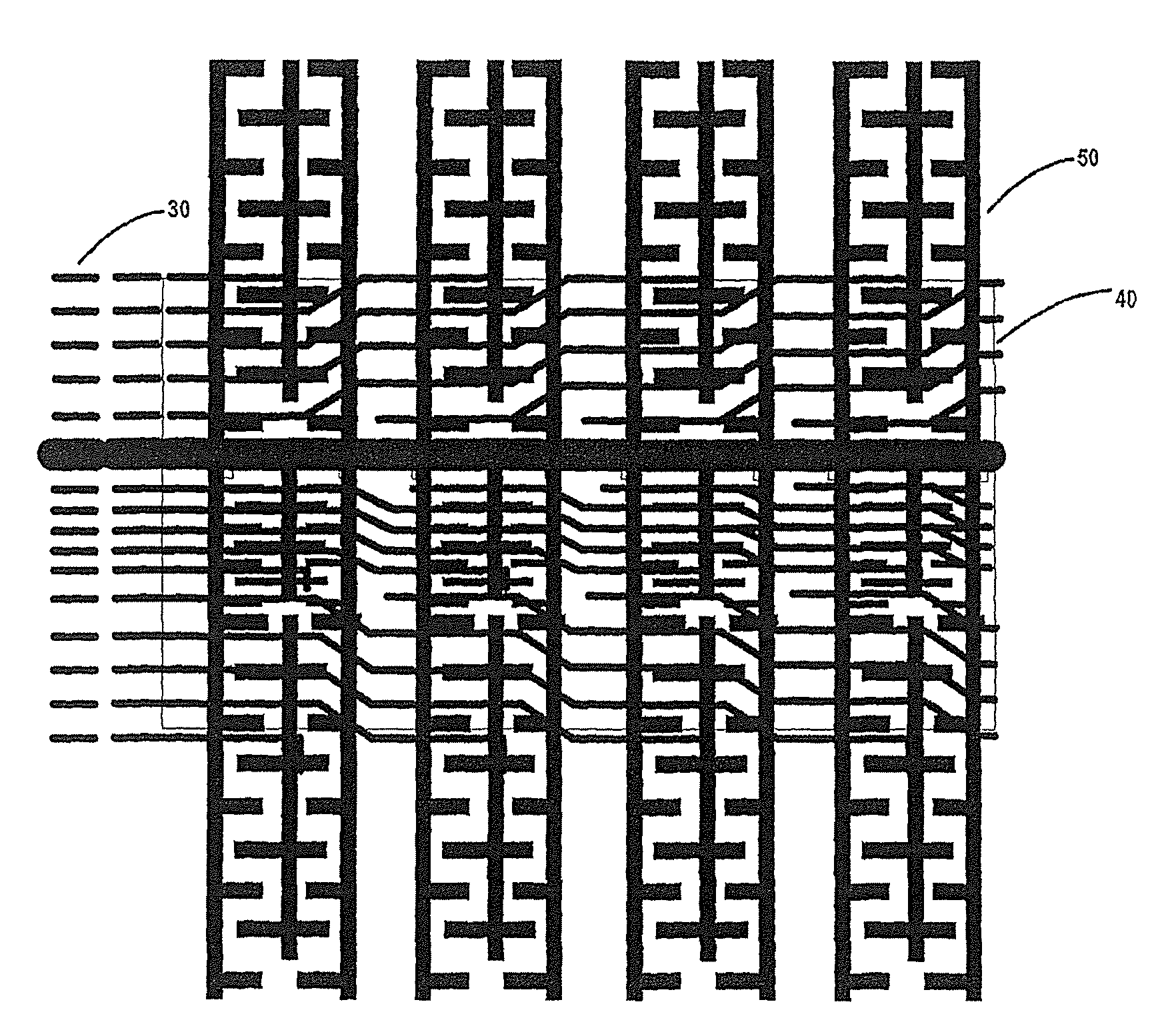
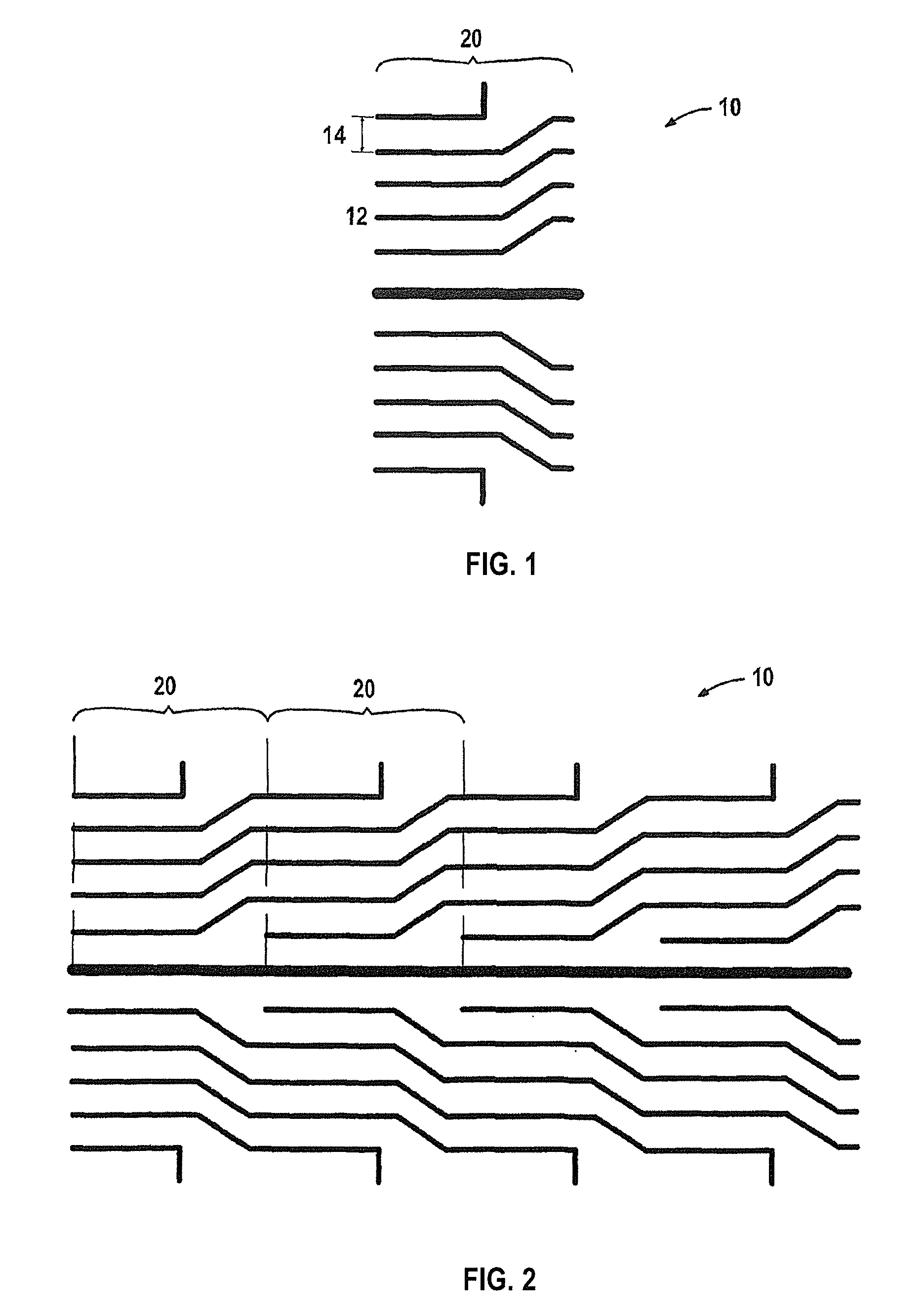
As illustrated in FIG. 1, each sensor 10 comprises sections 20 that are fairly short in length and thus easy to print in a repetitive manner; such a length, for example, may be 1′. Each sensor section 20 may comprise a separate analog output. Separate sensor areas permit one to distinguish between different force or pressure events (for example, a ball impact and foot step) that can happen at the same time on separate areas of one particular sensor. They also allow one to localize the location of an event to within the area of a sensor, and in case of failure of a sensor area, only one small area would be affected. This idea of splitting up a sensor into smaller sensor areas is described in U.S. Pat. No. 3,982,759 (Grant).

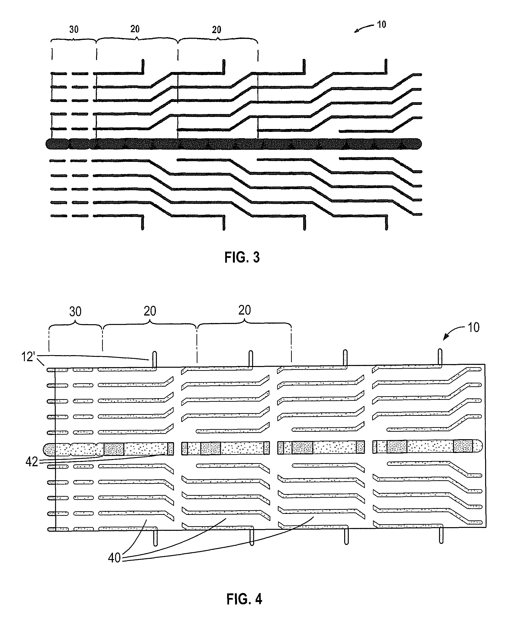
Because of the desired length of the long sensors 10, they can only be printed if the artwork or layout design has a repeating pattern. The following discussion and references to the Figures illustrate how this is done.

First, a series of conductive traces 12 are pr...


PUM

PropertyMeasurementUnit
Lengthaaaaaaaaaa
Forceaaaaaaaaaa
Dielectric polarization enthalpyaaaaaaaaaa

Abstract

A force or pressure sensor and appertaining method for manufacturing are provided in which the sensor comprises a repeating conductive trace pattern that can be replicated to produce a consistent conductive trace across more than one adjacent pattern section forming an electrical bus, wherein more than one section of a series of conductive traces are printed on a thin and flexible dielectric backing using the pattern. The thin and flexible dielectric backing has a repeated pattern of conductive traces printed above the dielectric backing and one or more dielectric layers provided above the conductive traces, the dielectric layers having access regions permitting contact of conductors above the one or more dielectric layers, and a sensor conductor layer printed above the one or more dielectric layers that contacts the conductive traces via at least one of the access regions or regions not covered by the one or more dielectric layers.

Description

BACKGROUNDThe present invention relates to a method for manufacturing long force sensors with a repeated design pattern using screen printing or other repetitive printing technology. Sensors produced according to the method do not have any practical limitation on length.Such sensor technology is desirable in situations in which a lengthy sensor construction is needed. For example, in a tennis court, it is desirable to automate line calling, which is the detection as to whether a tennis ball impacts the ground at an in-bounds location or an out-of-bounds location. Flat force detecting sensors may be utilized at the boundaries to make a determination of the point of ball impact. An exemplary use of such sensors is described in the U.S. patent application Ser. No. 11 / 917,802, herein incorporated by reference.Because of the tennis court size, sensors have to be manufactured extremely long (up to 60′ long). In principle, one could simply create and utilize sensors having a length of, e.g...

Claims


Application Information

Patent Timeline
IPC IPC(8): G01D7/00G01L1/04G01R3/00
CPCA63B71/0605A63C19/065A63B2071/0611Y10T29/49128Y10T29/49103Y10T29/4913Y10T29/49007Y10T29/49826
Inventor ROSENBERG, ILYA D.
Owner ROSENBERG ILYA D
Why Eureka
Try Eureka