RF heater arrangement for substrate heating apparatus

a heater arrangement and substrate technology, applied in the direction of coatings, metallic material coating processes, chemical vapor deposition coatings, etc., can solve the problems of inability to provide stably these temperature levels for prolonged periods of time, failure of materials to be properly deposited on the substrate, and inability to maintain the temperature level for a long time. , to achieve the effect of reducing levitation, reducing the number of rf heaters, and reducing the number of rf heater

Inactive Publication Date: 2011-07-26
STRUCTURED MATERIALS
View PDF7 Cites 9 Cited by
  • Summary
  • Abstract
  • Description
  • Claims
  • Application Information

AI Technical Summary

Benefits of technology

[0006]The present invention provides an improved RF heating system for a substrate or substrates including a susceptor for supporting the substrate; one or more RF heating coils; and a platen disposed between the RF heating coil and the substrate. The platen is constructed of materials that become heated under RF energy, which will then radiate heat into the susceptor and the substrate. In this way the susceptor need not be constructed of materials that become heated under RF energy thus minimizing levitation. Further, the susceptor may also be made of more inert, higher thermal conductivity, or purer materials, having beneficial properties not realizable from metal. Two such susceptor materials are diamond and alumina for maximum thermal conductivity in an RF headed susceptor-platen system for single or multiple wafers of 2″ to 20″ (or larger) diameter with the susceptor preferably of at least 0.040″ thickness. The platen also provides a uniform temperature profile across the substrates, benefiting from a more diffused heat source. Additionally, the region around the directly RF heated platen can be independently purged to minimize any potential outgassing contaminants.

Problems solved by technology

Conventional resistive heating elements, made of graphite or tungsten, cannot stably provide these temperature levels for prolonged periods of time.
However conventional induction heating systems are subject to a number of is problems which can lead to failure of the materials to be properly deposited on the substrates.
A serious problem is a non uniform temperature profile across the substrates which is caused by factors including some or all of the following: non-uniform induced current heating (i.e. local hot or cold zones), variations in thermal radiation (i.e. sides versus top and bottom surfaces), and irregular configuration of the susceptor among others.
These factors can cause an uneven deposition of the materials and / or a failure or certain materials to be deposited at all.
Another problem is that conventional induction heating systems require that the susceptor be conductive (metallic) which can result in induced currents in the wafer, causing the mounted substrates to levitate away from the susceptor, or cause the susceptor to warp, again leading to uneven thermal contact to the wafer and thus uneven heating or even a tossing away of the wafer, and contamination directly to the depositing film from the outgassing of the metals / conductors being heated.

Method used


Image

  • RF heater arrangement for substrate heating apparatus
  • RF heater arrangement for substrate heating apparatus
  • RF heater arrangement for substrate heating apparatus

Examples


Embodiment Construction

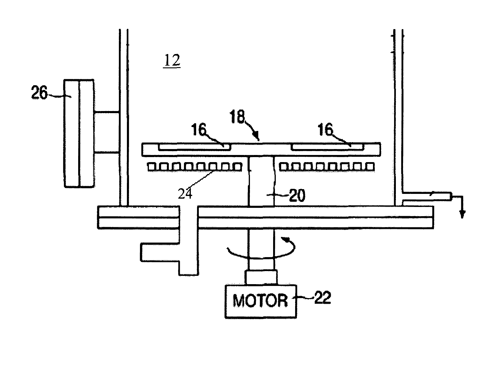
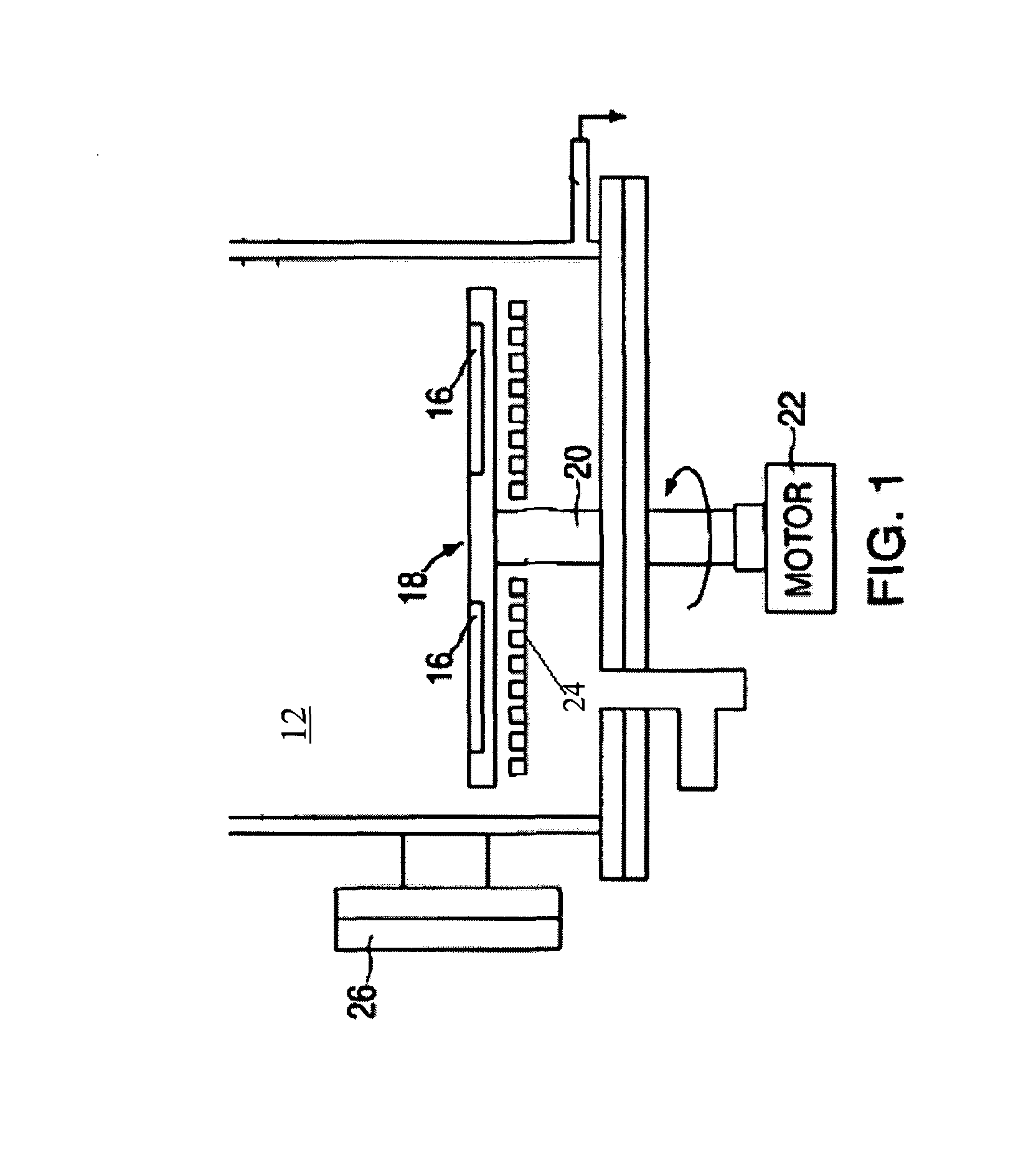
[0014]FIG. 1 illustrates a Chemical Vapor Deposition (CVD) System 10 which, in general overview: includes a reactor chamber 12, sealed to the atmosphere, in which is mounted a distribution housing (a showerhead, which would be located at the top in this example—but is not shown herein) for the film growth reactant gases. The distribution housing directs the reactant gases over one or more substrate wafers 16, mounted, in this example, on a rotatable susceptor 18 which is rotated through a shaft 20 by a motor 22 mounted externally from reactor chamber 12, and which are to heated by a heater unit 24 which may be either a resistive heating element or an induction RF heating coil. In an RF heating system the magnetic field generated by the RF coil induces eddy currents in susceptor 18 which cause it to become heated along with the wafers mounted thereon. The reactant and carrier gases generated by external sources (not shown) are distributed though distribution housing 14 and flow over ...


PUM

PropertyMeasurementUnit
RF energyaaaaaaaaaa
electrically insulatingaaaaaaaaaa
thermal conductivityaaaaaaaaaa

Abstract

An RF heating system for a substrate or substrates including a susceptor for supporting the substrate; one or more RF heating coils; and a platen disposed between the RF heating coil and the substrate. The platen is constructed of materials that become heated under RF energy, which will then radiate heat into the susceptor and the substrate. In this way the susceptor need not be constructed of materials that become heated under RF energy thus minimizing levitation. The platen provides a uniform temperature profile across the substrates, benefiting from a more diffused heat source. The RF heating system may also be utilized in CVD apparatus that deposits materials on a continuous tape or roll.

Description

REFERENCE TO RELATED APPLICATIONS[0001]This application claims priority from U.S. provisional application Ser. No. 60 / 789,953 filed Apr. 6, 2006BACKGROUND AND SUMMARY OF THE INVENTION[0002]This application is directed to substrate heating apparatus within the preferred embodiment of Chemical Vapor Deposition (CVD) apparatus and more specifically to an improved arrangement for RF heating of the substrate in a deposition reactor.[0003]Chemical Vapor Deposition (CVD) systems are widely used to deposit compositional and compound films in the manufacture of electronic devices, such as integrated circuits formed by the sequential or simultaneous deposition of compounds upon a heated substrate, which is usually in the form of a wafer that is typically mounted on a rotatable or non-rotatable susceptor. The reactants are transported to the surface in the gas phase by typically one or more carrier gases. The elements deposit on the wafer surface, forming the desired compound and the undesirab...

Claims


Application Information

Patent Timeline
Patent Type & Authority Patents(United States)
IPC IPC(8): C23C16/00
CPCC23C16/4586C23C16/46H01L21/67109H01L21/68764H01L21/68771H01L21/68792
Inventor TOMPA, GARY S.
Owner STRUCTURED MATERIALS
Why Eureka
Try Eureka