Restraining device for reducing warp in lumber during drying

Inactive Publication Date: 2011-08-02
ERICKSON ROBERT W
View PDF399 Cites 17 Cited by
  • Summary
  • Abstract
  • Description
  • Claims
  • Application Information

AI Technical Summary

Benefits of technology

[0008]A restraint device is provided that corrects the problem of excessive warping, especially crook, of dimension lumber as the lumber is dried. Lumber pieces are placed side by side to create horizontal courses which are then loaded and held clamped edge to edge with a horizontal force, that is, a force parallel to the wide faces (width) of the lumber pieces. The force thus is perpendicular to the edge (narrow side) of each course and is sufficiently large to hold the pieces of lumber warp free as they are dried. Courses (horizontal layers) of individual lumber pieces are laid down, and the courses are separated vertically by stickers to provide a space for air flow between the courses. The space between courses has a plane and the clamping force is parallel to the plane of the air flow space and parallel to the lumber courses. The horizontal load is of a magnitude to provide a side or edge force resisting any crooking or slippage of the lumber pieces one upon another. The restraint system takes up or prevents the spaces between the edges of adjacent lumber pieces that occur in contemporary drying as a consequence of the unavoidable width shrinkage of individual lumber pieces.

Problems solved by technology

The restraint system takes up or prevents the spaces between the edges of adjacent lumber pieces that occur in contemporary drying as a consequence of the unavoidable width shrinkage of individual lumber pieces.

Method used


Image

  • Restraining device for reducing warp in lumber during drying
  • Restraining device for reducing warp in lumber during drying
  • Restraining device for reducing warp in lumber during drying

Examples


Embodiment Construction

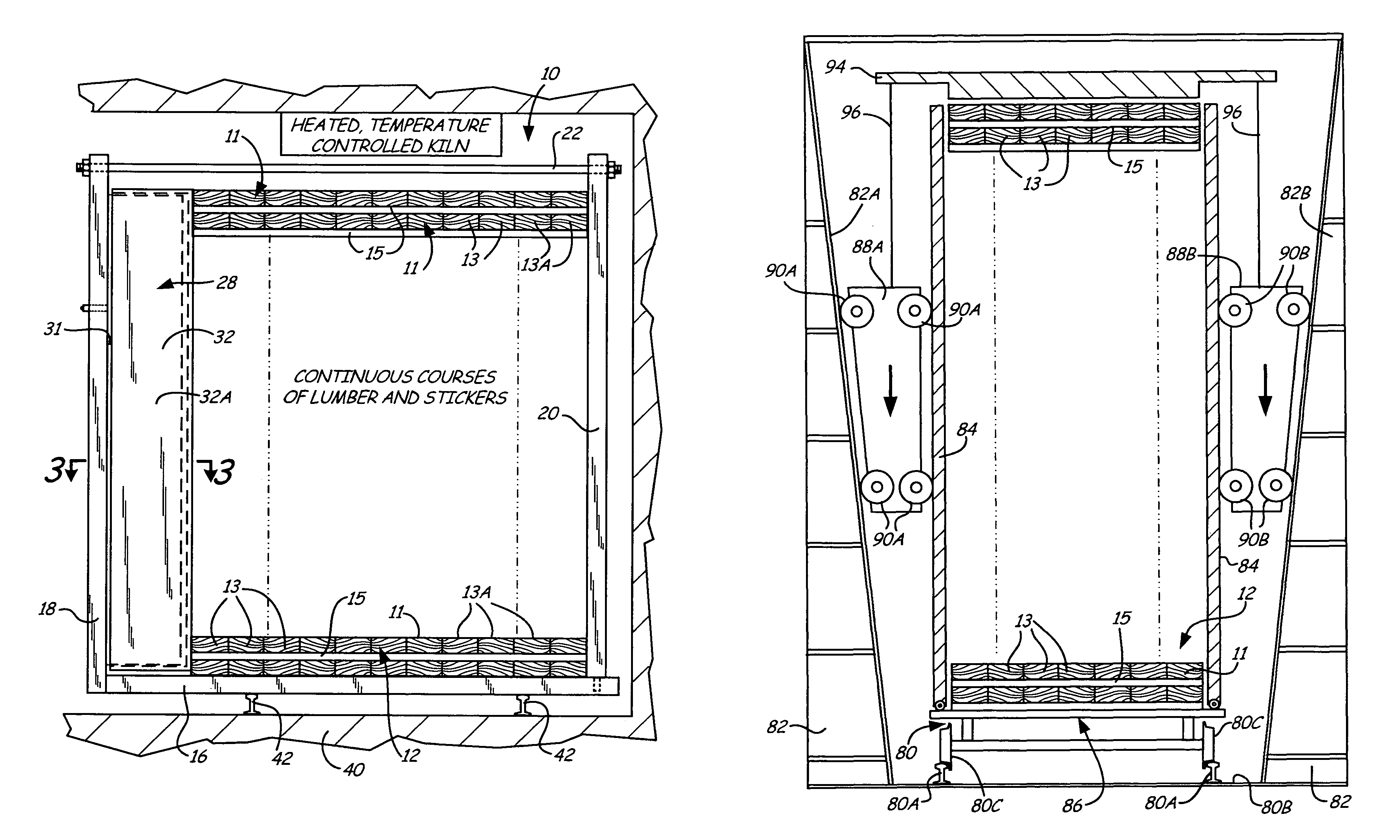
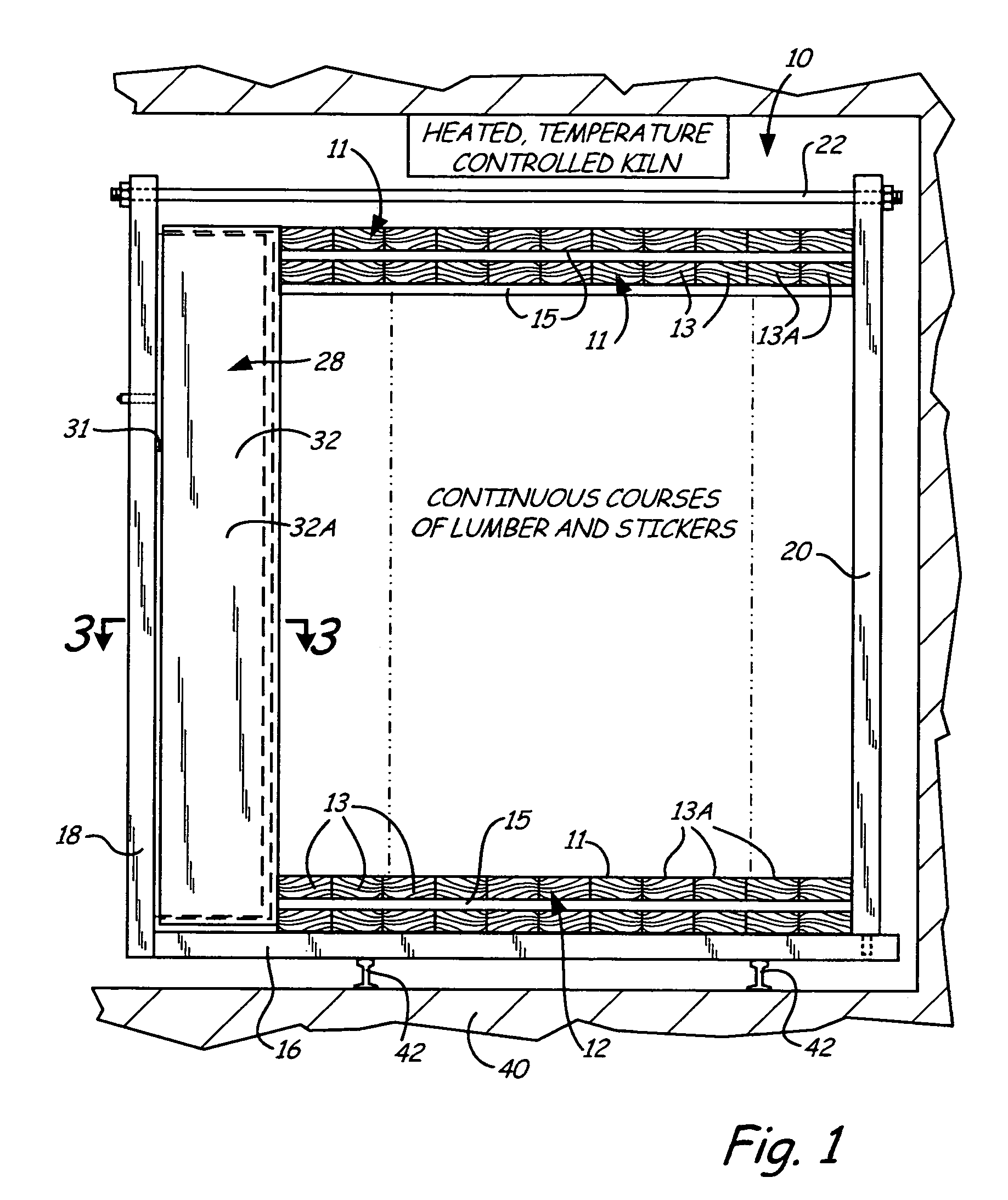
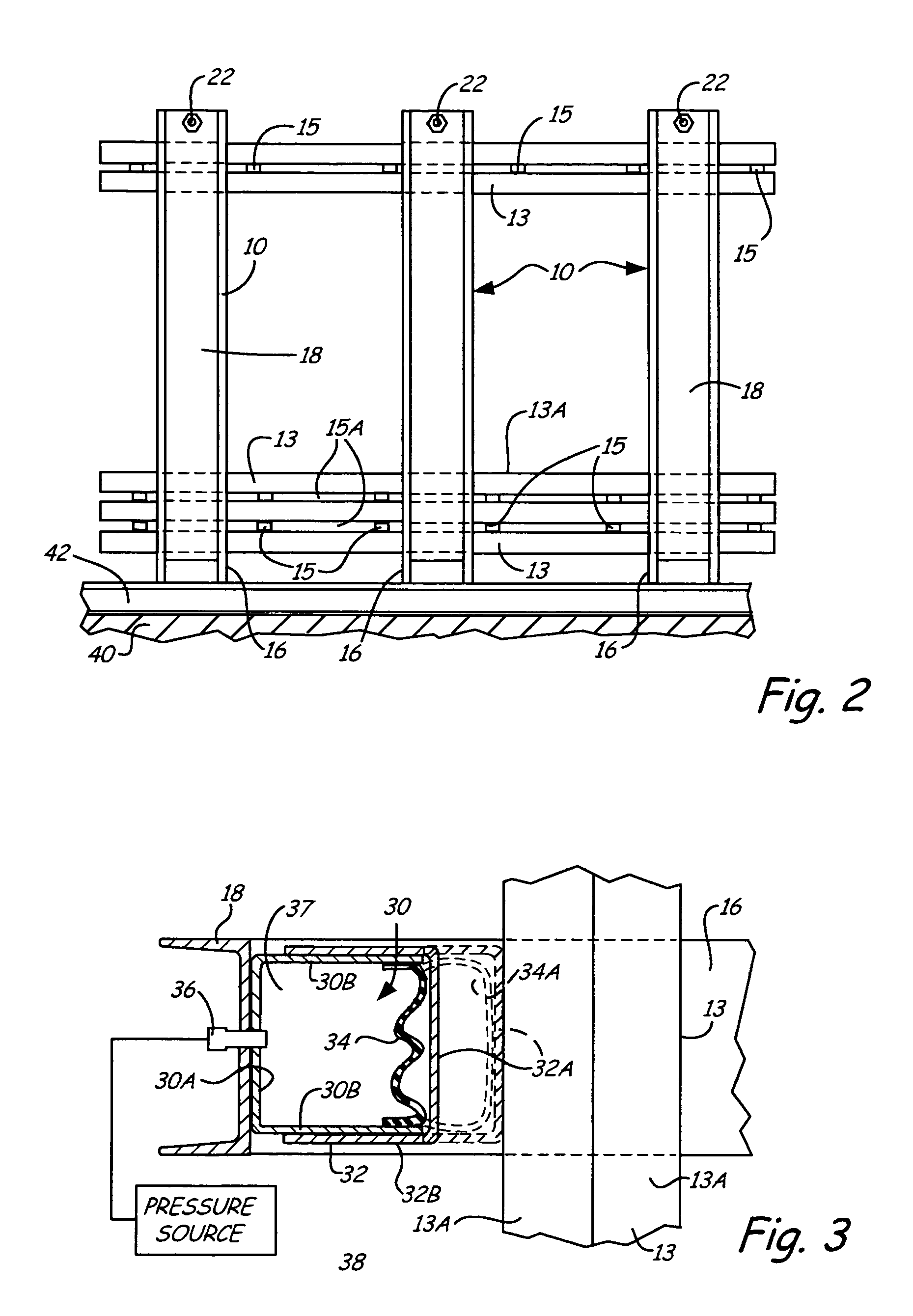
[0018]The general concept of the present invention is set forth in FIG. 1, wherein a unit or stack of lumber 12 in a view is contained within a plurality of quadrangle (four sided) restraining frames or devices 10. Each quadrangle frame 10 is designed to employ a selected one of a variety of force applicators to provide continuous, edge wise pressure or force on the individual horizontal courses 11 (horizontal layers) of individual lumber pieces 13 that make up the stacked unit 12. The individual lumber pieces 13 of each course are laid edge to edge so that the wide face or width 13A is horizontal. The courses are separated by stickers or spaces 15 to form an air flow space of channel 15A between and parallel to the plane of the course of lumber pieces. The quadrangle frame 10 consists of vertical and horizontal steel components, including a horizontal base, comprising a base channel 16 that has an upright channel or member 18 fixed to one end to form a lumber unit support. The quad...


PUM

PropertyMeasurementUnit
lengthaaaaaaaaaa
lengthaaaaaaaaaa
lengthaaaaaaaaaa

Abstract

The present invention relates to an apparatus and processing method for drying lumber, for example two-by-four studs in an environment in a kiln in a manner to avoid warping, including crook, bow, cup and twist. The lumber pieces are stacked in a normal manner with stickers for providing air flow between courses of the lumber pieces, and the stack is dried while a horizontal force is provided to the respective courses of lumber in the stack to hold the individual pieces of lumber in edge to edge contact throughout the drying, equalizing, conditioning and cooling process for first drying of lumber, redrying of lumber or in a treatment process for removing warp from previously dried lumber. A vertical force comprising a weight or other force generating device can be also applied to the stack of lumber to augment the overall reduction in warpage if so evidenced.

Description

[0001]This application refers to and claims priority from U.S. Provisional Application Ser. No. 60 / 561,424, filed Apr. 12, 2004, the entire content of which is incorporated herein by reference.BACKGROUND OF THE INVENTION[0002]The present invention relates to a restraining and force applying device that is used during a drying process for lumber pieces to reduce warp, that is, reducing the amount of crook, twist, bow and cup, of the dried lumber pieces. The device applies horizontal force to clamp together the edge surfaces of the individual lumber pieces placed edge to edge in courses of lumber pieces, and maintains these clamping forces throughout the drying process and, if required, while the lumber cools. The horizontal force is parallel to the width face of the lumber, and thus to the plane of the course of lumber as opposed to vertical forces parallel to the narrower edge surfaces of lumber pieces and perpendicular to the plane of the lumber courses. A vertical force also can b...

Claims


Application Information

Patent Timeline
Patent Type & Authority Patents(United States)
IPC IPC(8): F26B19/00B27K5/00F26B7/00F26B9/04F26B25/06F26B25/08
CPCF26B7/00F26B9/04F26B25/08F26B2210/16
Inventor ERICKSON, ROBERT W.
Owner ERICKSON ROBERT W
Why Eureka
Try Eureka