Hydrocarbon recovery process

a technology of hydrocarbon recovery and water treatment, applied in the direction of fluid removal, survey, borehole/well accessories, etc., can solve the problem that low salinity waters are often not available at a well site, and achieve enhanced oil recovery, low salinity, and better oil recovery

Active Publication Date: 2011-08-02
BP EXPLORATION OPERATING CO LTD +1
View PDF17 Cites 22 Cited by
  • Summary
  • Abstract
  • Description
  • Claims
  • Application Information

AI Technical Summary

Benefits of technology

[0008]It has now been found that by manipulating the total multivalent cation concentration of a low salinity injection water and by injecting a minimum pore volume of the manipulated low salinity water into an oil-bearing formation that the residual oil saturation of the formation may be reduced in comparison to injecting the original low salinity water or a higher salinity water. In particular, it has been found that the key to better oil recovery is use of an injection water of a special lower multivalent cation content where the total dissolved solids content (TDS) of the injection water is in the range of 200 to 10,000 ppm. It has also been found that enhanced oil recovery using a low salinity water is dependent upon the nature of the formation.
[0043]The person skilled in the art will understand that in secondary recovery, a fluid is injected into the formation from an injection well in order to maintain the pressure in the formation and to sweep oil towards a production well. An advantage of injecting the aqueous displacement fluid into the formation during secondary recovery, is that the aqueous displacement fluid has been either formulated or selected so as to release additional oil from the surface of the pores of the formation (compared with injection of water having a higher TDS content and / or higher multivalent cation content). Accordingly, there may be a longer period of dry oil recovery from the production well thereby deferring water break-through. In addition, even after water break-through, there will be enhanced recovery of oil compared with using a water of higher TDS content and / or higher multivalent cation content.
[0044]The person skilled in the art will understand that in tertiary recovery, injection of the original fluid is stopped and a different fluid is injected into the formation for enhanced oil recovery. Thus, the fluid that is injected into the formation during tertiary recovery is the aqueous displacement fluid of selected TDS content and selected multivalent cation content, and the fluid that has previously been injected into the formation during secondary recover may be a water having a higher TDS content and / or higher multivalent cation content than the aqueous displacement fluid (for example, seawater and / or a produced water). Thus, an advantage of injecting the aqueous displacement fluid during tertiary recovery is that this results in enhanced oil recovery.
[0046]In a further preferred embodiment of the present invention there is provided a method for increasing the recovery of crude oil from a reservoir comprising at least one porous and permeable subterranean formation wherein (a) the formation comprises a sandstone rock and at least one mineral that has a negative zeta potential under the reservoir conditions, (b) crude oil and connate water are present within the pores of the formation, and (c) an aqueous displacement fluid is injected into the formation for displacing crude oil from the surface of the pores of the formation, wherein the aqueous displacement fluid is selected by:(a) determining the multivalent cation content of the connate water; and

Problems solved by technology

The factors that control crude oil / brine / rock interactions and their effect on wettability and oil recovery involve complex and sometimes competing mechanisms.
But lower salinity waters are often not available at a well site and would have to be made by reducing the total ion concentration of higher salinity water using techniques such as reverse osmosis or forward osmosis.
There is thus a problem of how to enhance recovery of oil from an oil-bearing formation using a method which is either cheaper for the same recovery or which gives better oil recovery for the same cost.

Method used


Image

  • Hydrocarbon recovery process
  • Hydrocarbon recovery process
  • Hydrocarbon recovery process

Examples


example 8

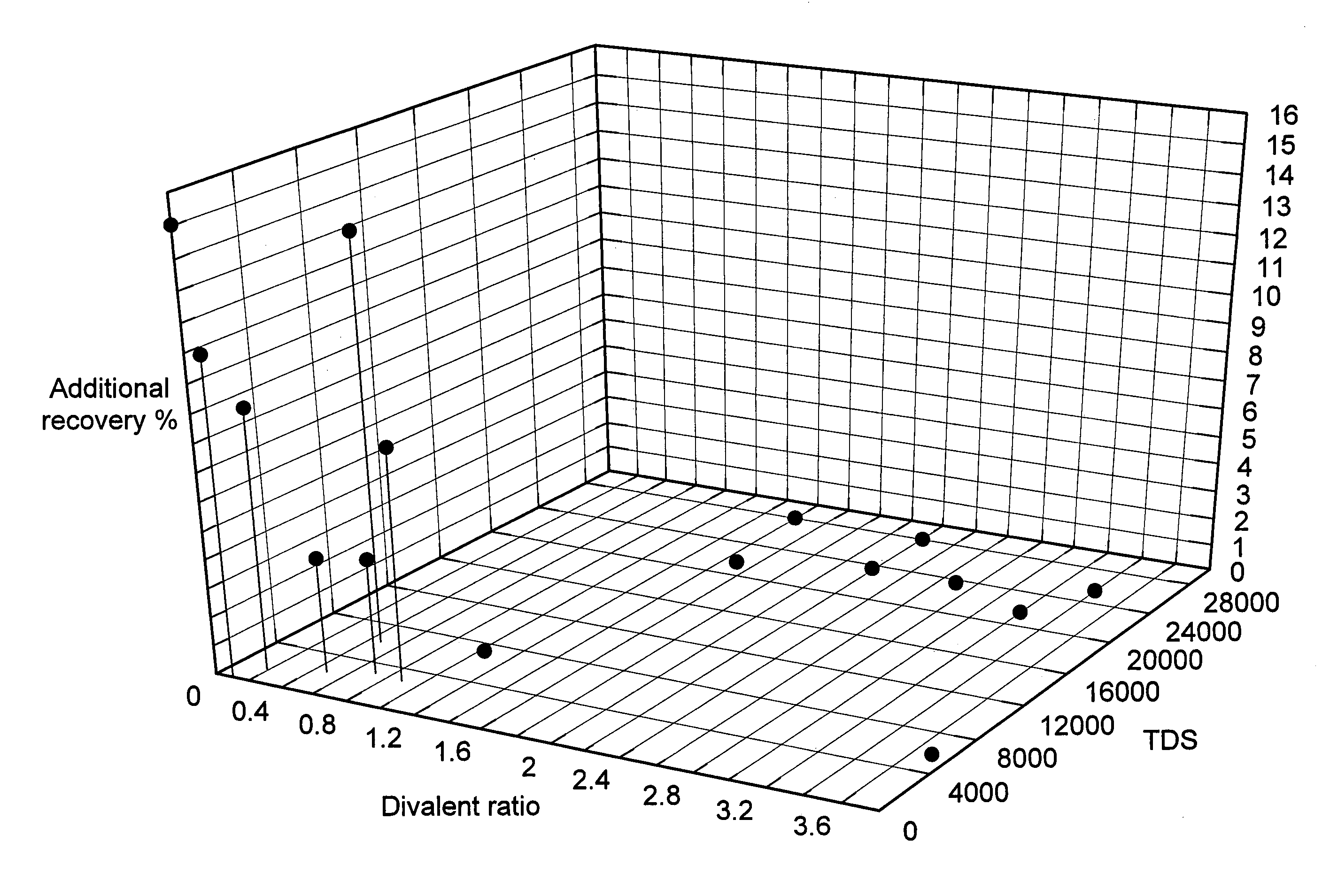
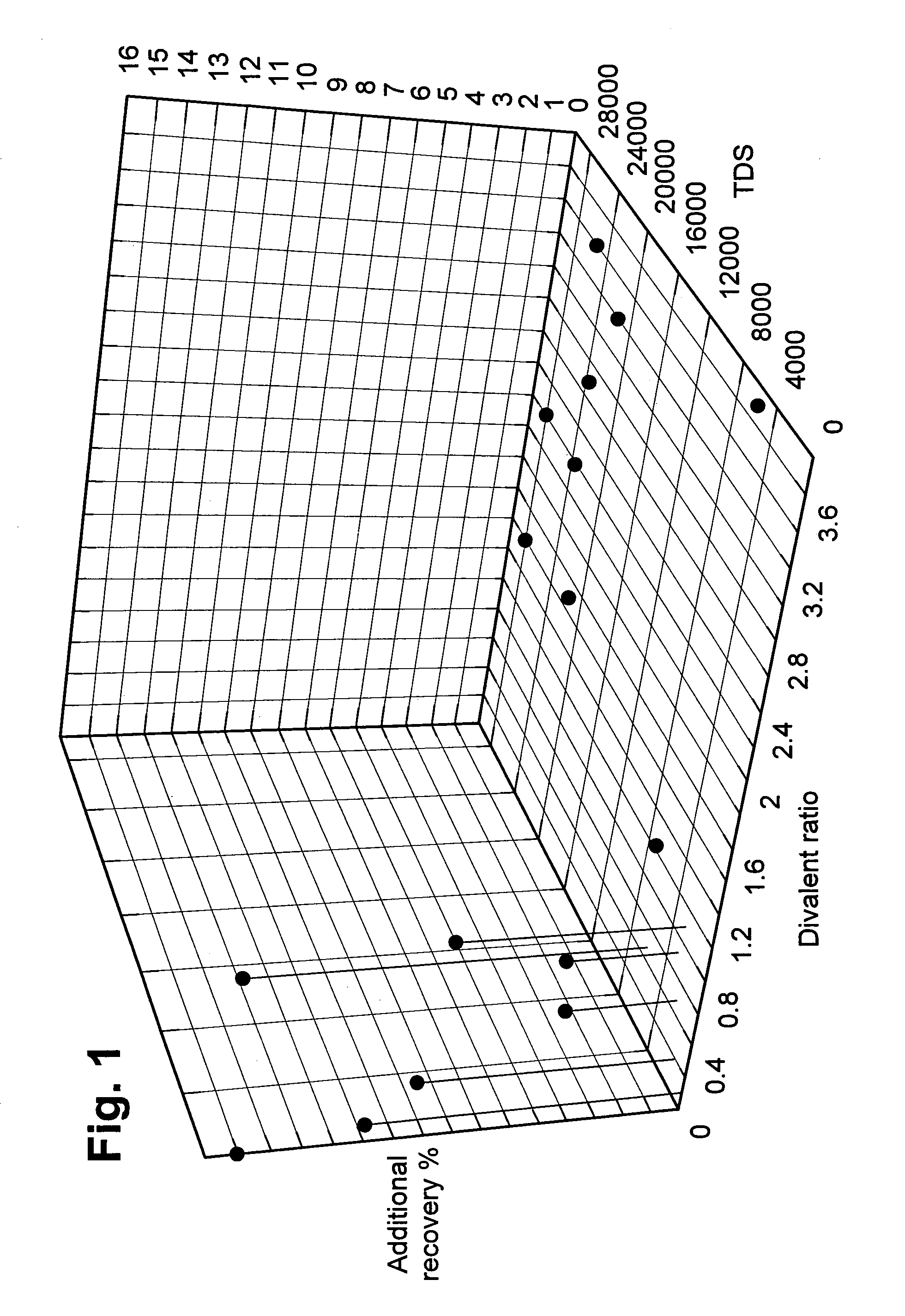
[0062]The SWCTT tests of Examples 1-7 were repeated with a number of different sized slugs of the aqueous displacement fluid (injection water) of analysis Ca 1.47 ppm / Mg 0 ppm / Divalent TDS 10 ppm. The connate water contained Ca 320 ppm / Mg 48 ppm / Divalents 398 ppm / TDS 31705 ppm giving the divalent fraction of 0.003. The oil had an API gravity of 23°. The formation contained 13.8% kaolinite.

[0063]Produced water, which was the connate water in the test, was passed into the formation first, giving an Sor of 0.42. A slug of 0.2 PV of the injection water was then passed giving an Sor of 0.42 followed by a repeat slug of the produced water. A slug of 0.4 PV of the injection water was then passed giving an Sor of 0.27, followed again by a slug of the produced water. The Sor was at 0.27 after a slug of 0.7 PV of the injection water was passed again followed by produced water. The Pore Volume, PV, was determined from modelling studies.

example 9

[0064]The SWCTT tests of Ex 8 were repeated with a number of different sized slugs of the aqueous displacement fluid (injection water) of analysis Ca 30 ppm / Mg 6 ppm / Divalent 37 ppm TDS. The connate water was the same as in Ex 8 giving the divalent fraction of 0.09. The oil had an API gravity of 23°. The formation contained 12.2% kaolinite.

[0065]Produced water, which was the connate water in the test, was passed into the formation first, giving an Sor of 0.41. A slug of 0.2 PV of the injection water was then passed giving an Sor of 0.37, followed by a repeat slug of the produced water. A slug of 0.3 PV of the injection water was then passed giving an Sor of 0.30, followed again by a slug of the produced water. The Pore Volume, PV, was determined by modelling studies.

example 10

[0066]The following studies utilized a coreflood facility which operates at reservoir conditions, of up to 150° C. and 10,000 psi. The equipment of the coreflood facility has an in-situ saturation monitor (described below) and uses live fluids (reservoir fluids that are equilibrated with reservoir gas) both for ageing and fluid flow. Volumetric production is measured at the reservoir conditions using an in-line separator. Saturations during and at the end of the flood are assured by measuring the amount of the pore space occupied by radioactively doped brine. The in-situ saturation monitor not only determines the saturation but also provides a quantitative analysis of the integrity of the slug, due to the difference in capture cross section between high salinity radioactively-doped brines and low salinity brines.

Core Preparation

[0067]Core plug samples, nominally 3″ long by 1½″ in diameter were used for this study. The samples were first restored i.e. the samples were cleaned using m...


PUM

PropertyMeasurementUnit
pressureaaaaaaaaaa
temperatureaaaaaaaaaa

Abstract

Method for increasing the recovery of crude oil from a reservoir containing at least one porous and permeable subterranean formation wherein the formation includes sandstone rock and at least one mineral that has a negative zeta potential under the reservoir conditions and wherein crude oil and connate water are present within the pores of the formation. The method is carried out by (A) injecting into the formation a slug of an aqueous displacement fluid that displaces crude oil from the surface of the pores of the formation wherein the pore volume (PV) of the slug of the aqueous displacement fluid is at least 0.2 and less than 1 and the aqueous displacement fluid has a total dissolved solids (TDS) content in the range of 200 to 10,000 ppm and the fraction of the total multivalent cation content of the aqueous displacement fluid to the total multivalent cation content of the connate water is less than 1, and (B) subsequently injecting into the formation a drive water of higher multivalent cation content and / or higher total dissolved solids content than the aqueous displacement fluid.

Description

[0001]This application is the U.S. national phase of International Application No. PCT / GB2007 / 003337, filed 5 Sep. 2007, which designated the U.S. and claims priority to U.S. Application No. 60 / 843,000, filed 8 Sep. 2006, the entire contents of each of which are hereby incorporated by reference.[0002]The present invention relates to a method for recovering hydrocarbons from a porous and permeable subterranean hydrocarbon-bearing formation by injecting a low salinity water into the formation.BACKGROUND OF THE INVENTION[0003]It has long been known that only a portion of the oil can be recovered from an oil-bearing subterranean formation as a result of the natural energy of the reservoir. So-called secondary recovery techniques are used to force more oil out of the reservoir, the simplest method of which is by direct replacement with another medium, usually water or gas.[0004]Water-flooding is one of the most successful and extensively used secondary recovery methods. Water is injected...

Claims


Application Information

Patent Timeline
Patent Type & Authority Patents(United States)
IPC IPC(8): E21B43/20E21B43/22E21B49/00C09K8/58
CPCC09K8/58E21B43/20Y10S507/904Y10S507/936C09K8/60E21B43/16
Inventor COLLINS, IAN RALPHJERAULD, GARY RUSSELL
Owner BP EXPLORATION OPERATING CO LTD
Why Eureka
Try Eureka