
Shock wave therapy device with image production

a technology of shock wave and image, applied in the field of shock wave therapy devices, can solve the problems of ineffective treatment with an increased risk of side effects, deviation between the displayed and actual focus position, and the focus of the physical shock wave not proven and displayed using measurement technology, and achieve the effect of cost-effectiveness

Active Publication Date: 2011-08-02
DORNIER MEDTECH SYST GMBH
View PDF166 Cites 6 Cited by
  • Summary
  • Abstract
  • Description
  • Claims
  • Application Information

AI Technical Summary

Benefits of technology

[0010]The object of the present invention is to provide a shock wave therapy device and a method with which the position of the focus and the concrement or the target area can be monitored as cost-effectively as possible and in a way that is as least susceptible to errors as possible. This object is solved by a shock wave therapy device according to the claims herein.
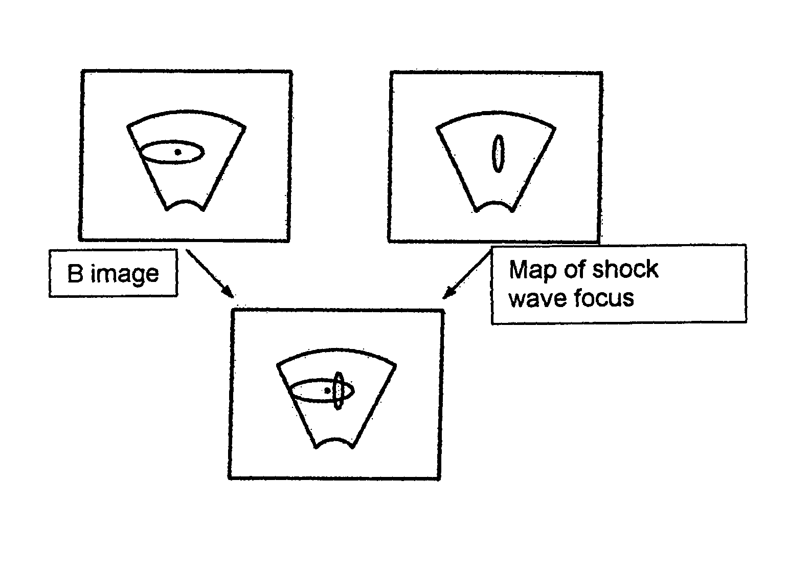
[0011]The shock wave therapy device also uses the same ultrasound unit that is used for normal image production to register components of the shock wave for obtaining image information which are reflected or scattered in the focus area of the shock wave. Therefore, it is possible to obtain an image of the shock wave focus itself. Because this shock wave focus is received with the same ultrasound unit as the normal image, optimum monitoring of the treatment is possible. The shock wave focus can be aligned with the target area or concrement without any doubt. Detection of the shock wave focus ensures that the acoustic energy of the therapy wave reaches the target.
[0012]The ultrasound unit comprises preferably an electrical transducer such as a piezoelectric transducer which can be electronically focused. This is made up of a large number of individual elements which are arranged as either a 1-dim or 2-dim array. This type of transducer allows a high-quality ultrasound image to be obtained in a way that is cost-effective.
[0017]For the operating staff, it is an advantage if the different image information obtained is overlapped or superimposed so that it is shown in a single image. In this way, it is, in particular, easily possible to achieve alignment of the shock wave focus with the concrement.
[0019]Advantageously, a corresponding sensor is therefore provided with which the precise time of the shock wave source emission can be determined so that the electronics of the ultrasound unit can switch over accordingly to the reception of reflected or scattered components of the shock wave. Therefore, it is possible to achieve the most complete flow of image production possible, i.e. to ensure that image information can be obtained immediately before the emission of the shock wave by means of emission and reception of the ultrasound by the ultrasound unit.

Problems solved by technology

However, in German Patent DE 203 15 924 U1, the physical shock wave focus is not proven and displayed using measurement technology.
Therefore, incorrect adjustment of the mechanical coupling of the shock wave source can cause deviations between the displayed and actual focus positions.
This incorrect adjustment would lead to ineffective treatment with an increased risk of side effects.
In addition, it cannot be directly detected whether the shock wave is reaching the focus to a sufficient degree.
Faulty acoustic coupling between the shock wave and the body to be treated can weaken the shock wave energy applied.
Furthermore, faulty acoustic coupling can occur between the shock wave and strong reflections on, for example, ribs located above the target organ.
The disadvantage of this is that image production is only possible with application of a shock wave pulse, but not beforehand, to allow the shock wave source to be adjusted.
Furthermore, this method requires a shock wave therapy device to meet certain structural preconditions, such as the existence of a lens.
The disadvantage of this method is that no direct image production is possible, although this is a major advantage for carrying out lithotripsy, since direct image production can be used to determine the shape, size and state of disintegration of the concrement.
However, the disadvantage is that movements only occur in the case of cavitations which are, in themselves, unwanted, or only when the concrement is hit by the shock wave.
Otherwise, no movements can be detected and the method is no longer helpful.

Method used


Image

  • Shock wave therapy device with image production
  • Shock wave therapy device with image production
  • Shock wave therapy device with image production

Examples


Embodiment Construction

[0032]Referring to the drawings, in which like numerals represent like elements, aspects of the exemplary embodiments will be described herein below.

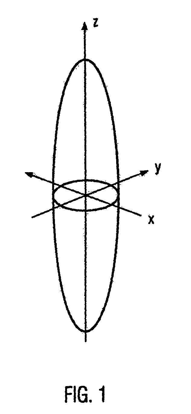
[0033]FIG. 1 shows the ellipsoidal isobars of a shock wave focus, for example, the −6 dB isobars relating to the focus tip value, which may be around 3 to 10 cm long in the Z direction and which is typically 2 to 15 mm wide in the X and Y direction.

[0034]The following description describes a lithotripter as an example of a shock wave therapy device. For the other treatment devices used in the treatment of pain, etc. (see above), the embodiments apply accordingly.

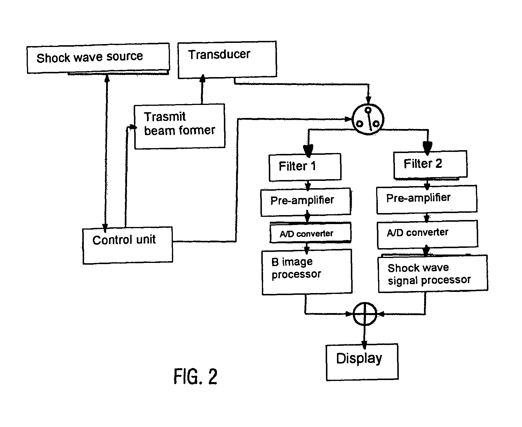
[0035]FIG. 2 shows the various elements of the lithotripter diagrammatically. The lithotripter comprises a shock wave source and a transducer which is used here as an ultrasound unit. The ultrasound unit can be positioned on or next to the symmetry axis of the shock wave source (see FIGS. 3 and 4). For example, the ultrasound unit can be a linear arrangement of 128 individual pi...


PUM


Abstract

The invention relates to a shock wave therapy device with a shock wave source for the emission of a shock wave and an ultrasound unit for obtaining image information by means of the emission and reception of ultrasound, whereby the ultrasound unit is provided for the reception of reflected or scattered components of the shock wave for obtaining image information. In addition, the invention relates to a method for obtaining image information for shock wave therapy with the steps: a) emitting ultrasound using an ultrasound unit, b) receiving the reflections of the emitted ultrasound using the ultrasound unit for obtaining image information, c) emitting a shock wave using a shock wave source and d) receiving reflected or scattered components of the shock wave using the ultrasound unit for obtaining image information.

Description

RELATED APPLICATION[0001]This application claims priority under 35 U.S.C. §119 (a) to German Patent Application No. 102005037043.8, filed on Aug. 5, 2005, which is incorporated herein by reference.FIELD OF THE INVENTION[0002]The invention relates to a shock wave therapy device with a shock wave source for the emission of a shock wave and an ultrasound unit for image production by means of emission and reception of ultrasound. Furthermore, the invention relates to a method of producing image information for shock wave therapy.BACKGROUND OF THE INVENTION[0003]In shock wave therapy, kidney or gall stones (concrements) are disintegrated by means of focused shock waves. Other forms of shock wave therapy are used for the treatment of pain, the treatment of closed vessels, the treatment of the cardiac muscle, in a corresponding target area. The shock wave source generally has a focus which is determined by its geometry. For example, the focus can be generated through a lens.[0004]In order ...

Claims


Application Information

Patent Timeline
IPC IPC(8): A61B8/00
CPCG01S15/899A61B8/0833A61B17/2255A61B17/2256G01S15/8925A61B17/22029A61B2019/5276A61B2019/5289G01S15/8918A61B2090/364A61B2090/378
Inventor BOHRIS, CHRISTIAN
Owner DORNIER MEDTECH SYST GMBH
Learn More