Sleeve unit, method of manufacturing thereof, and motor using the sleeve unit

a technology of sleeve unit and sleeve unit, which is applied in the direction of sliding contact bearings, manufacturing tools, transportation and packaging, etc., can solve the problems of severing the bearing unit, affecting the operation of the bearing unit, and the upper end surface in which the dynamic pressure generating grooves are formed, so as to prevent the degradation of the thrust dynamic pressure bearing and achieve the effect of preventing the degradation of the thrust dynamic pressure bearing and ensuring the quality of the bearing

Inactive Publication Date: 2011-08-02
NIDEC CORP
View PDF55 Cites 9 Cited by
  • Summary
  • Abstract
  • Description
  • Claims
  • Application Information

AI Technical Summary

Benefits of technology

[0010]According to the preferred embodiment of the present invention, the position of the upper bearing surface of the sleeve relative to the lower surface of the flange portion of the sleeve housing can be easily and accurately determined.
[0011]With the first bearing surface of the sleeve and the lower surface of the flange portion whose positional relationship is highly accurately determined, a clearance of a gap defined between the first bearing surface and a lower surface of the rotor hub opposing to the bearing surface via the gap is accurately maintained, preventing the degradation of a thrust dynamic pressure bearing.
[0012]With a sleeve unit manufactured by the method according to the preferred embodiments of the present invention, a motor having superior reliability and durability can be provided.

Problems solved by technology

However, when the upper end surface of the sleeve is arranged axially above the upper end surface of the housing, the upper end surface of the sleeve may come in contact with the lower surface of the rotor hub, and the upper end surface in which the dynamic pressure generating grooves are formed may be worn out.
The scratches and the damages on the surface in which the dynamic pressure generating grooves are formed may cause the seizure of the bearing unit and the like troubles.

Method used


Image

  • Sleeve unit, method of manufacturing thereof, and motor using the sleeve unit
  • Sleeve unit, method of manufacturing thereof, and motor using the sleeve unit
  • Sleeve unit, method of manufacturing thereof, and motor using the sleeve unit

Examples


first preferred embodiment

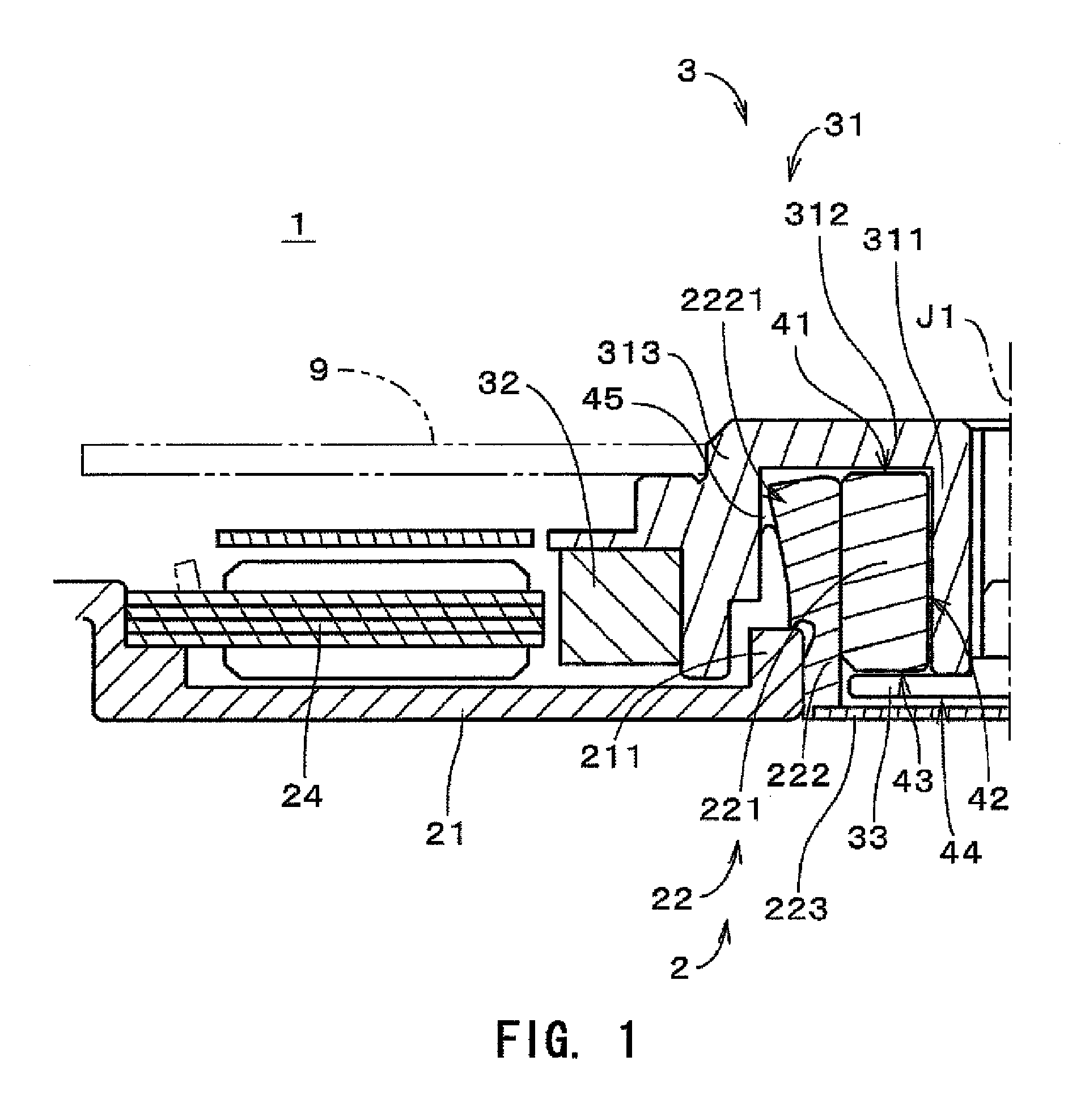
[0027]FIG. 1 is a vertical cross sectional view of a motor 1 for driving a data storage disk in a storage disk drive according to a preferred embodiment of the present invention. FIG. 1 shows only a left half of a cross section of the motor 1 including a central axis J1 (which is also a central axis of a sleeve unit 22 to be described later).

[0028]The motor 1 includes a static portion 2 as a stator assembly and a rotor portion 3. The rotor portion 3 is supported by the static portion 2 via a bearing assembly utilizing fluid dynamic pressure of lubricant so as to be rotatable around the central axis J1. In the following description, for convenience, a rotor portion 3 side along the center axis is referred to as an upper side of the motor 1, and a static portion 2 side along the center axis is referred to as a lower side of the motor 1, but does limit the orientation in an actual installation.

[0029]The rotor portion 3 includes a rotor hub 31 and a rotor magnet 32. A center of the roto...

second preferred embodiment

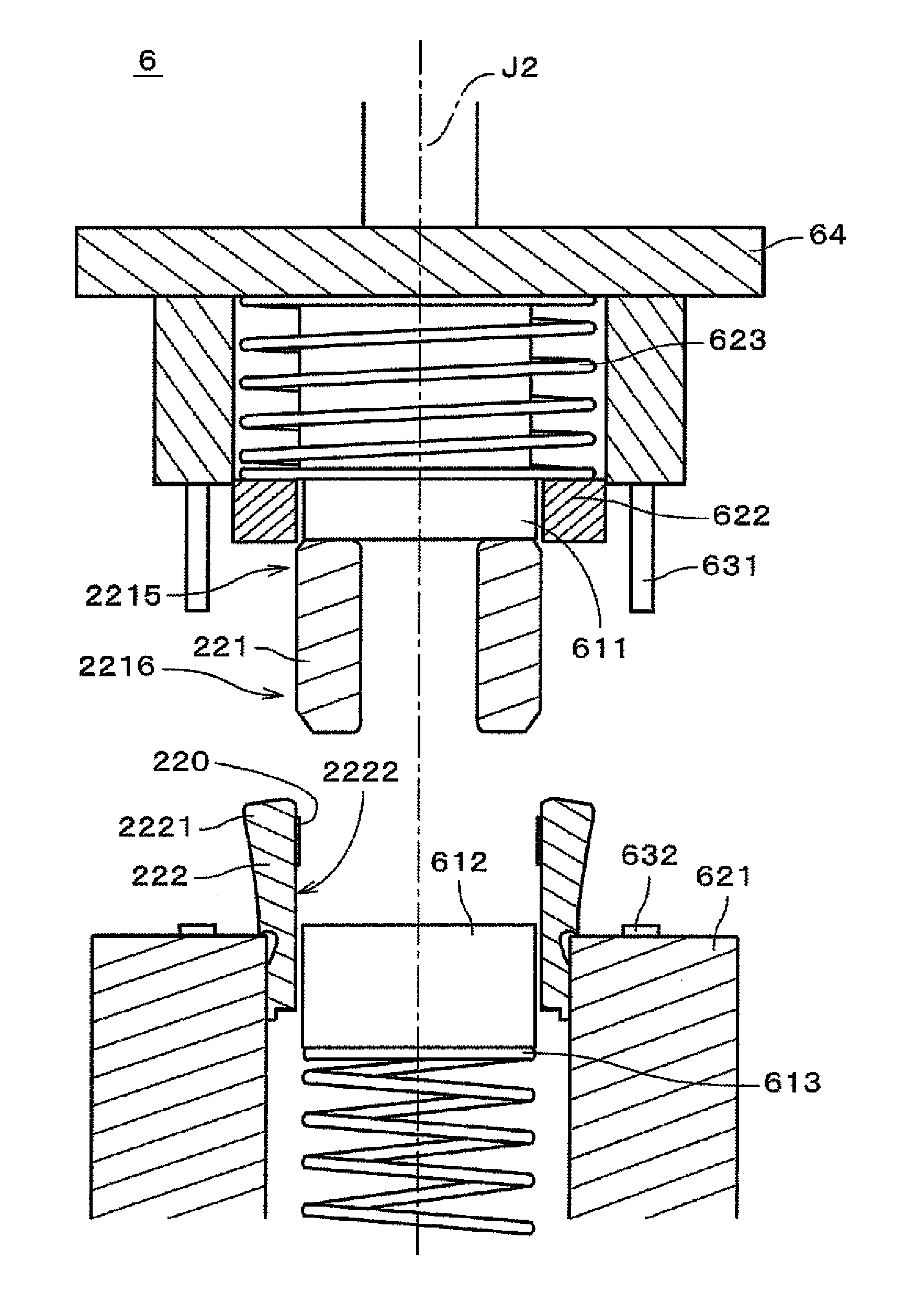
[0068]FIG. 7 is a chart illustrating a process flow of manufacturing the sleeve unit 22 according to a second preferred embodiment of the present invention, and FIGS. 8 and 9 are views illustrating manufacture of the sleeve unit 22. The configuration of the sleeve unit assembling device 6 according to the second preferred embodiment of the present invention will be approximately the same as that described in the detail description of the first preferred embodiment of the present invention, and detailed description will be made only of the features that are different. The configuration of the sleeve unit 22 to be manufactured and the motor 1 using the sleeve unit 22 according to the second preferred embodiment of the present invention is substantially the same as that described in FIG. 1.

[0069]In the present preferred embodiment of the present invention, an adhesive 320 which is different from that described in the first preferred embodiment of the present invention is used. The adhe...

third preferred embodiment

[0083]With reference to FIG. 10, a third preferred embodiment of the present invention will be described in detail. FIG. 10 is a cross sectional view illustrating a motor according to the third preferred embodiment of the present invention.

[0084]The motor according to the present preferred embodiment of the present invention includes a static portion 10, bearing assembly 12, and a rotor portion 14.

[0085]The static portion 10 includes a base plate 16 having a through hole arranged substantially the center thereof. In the through hole, the bearing assembly 12 is arranged and fixed to the base plate 16.

[0086]The bearing assembly 12 includes a sleeve 20 having a substantially cylindrical shape into which a shaft 22 is inserted, and a sleeve housing 18 having a substantially cylindrical shape with a base into which the sleeve 20 is arranged and fixed to the base plate 16 in the through hole.

[0087]The sleeve housing 18 includes a body portion 118 having a lower portion arranged in the thr...


PUM

PropertyMeasurementUnit
cure timeaaaaaaaaaa
cure timeaaaaaaaaaa
inner diameteraaaaaaaaaa

Abstract

An adhesive is applied to an inner surface of a sleeve housing, and a sleeve is relatively moved toward the sleeve housing from inserted into the sleeve housing. The adhesive is cured while a predetermined distance is maintained between a first bearing surface of the sleeve and a lower surface of a flange portion of the sleeve housing.

Description

BACKGROUND OF THE INVENTION[0001]1. Field of the Invention[0002]The present invention generally relates to a sleeve unit used for a fluid dynamic bearing assembly, a method of manufacturing the sleeve unit, and a motor using the fluid dynamic bearing assembly to which the sleeve unit is installed.[0003]2. Description of the Related Art[0004]Conventionally, a recording disk drive unit such as a hard disk device includes a spindle motor (hereinafter, simply referred to as “motor”) for rotary driving a recording disk. In such a bearing assembly utilizing fluid dynamic pressure, a thrust bearing portion or a radial bearing portion are formed with a shaft, a sleeve to allow the shaft to be inserted thereinto, and the like.[0005]The Japanese laid open patent publication No. 2003-262217 discloses a spindle motor having a bearing unit with a sleeve inserted in a sleeve housing and a shaft to a tip end of which a thrust plate is attached. In the spindle motor, thrust bearing portions are def...

Claims


Application Information

Patent Timeline
Patent Type & Authority Patents(United States)
IPC IPC(8): B29C65/00B31F5/00C09J5/06B32B37/00B29C67/00B65H29/00
CPCH02K5/1675H02K15/14Y10T29/49826Y10T156/1744F16C2380/26F16C17/107F16C33/08F16C2226/40
Inventor TAMAOKA, TAKEHITO
Owner NIDEC CORP
Why Eureka
Try Eureka