Power steering pump flow control

a technology of hydraulic pumps and flow control, which is applied in the direction of fluid couplings, positive displacement liquid engines, servomotors, etc., can solve the problems of lack of fluid in the chamber cavitating the pump, the fluid viscosity is too high to permit sufficient flow of fluid, and the pump is unable to maintain the flow rate. , to achieve the effect of reducing the pulsation of fluid, reducing the resistance to high viscosity fluid, and reducing the pulsation

Inactive Publication Date: 2011-08-09
FORD GLOBAL TECH LLC
View PDF5 Cites 2 Cited by
  • Summary
  • Abstract
  • Description
  • Claims
  • Application Information

AI Technical Summary

Benefits of technology

[0010]The flow control system of the present invention includes the addition of a multiple passage orifice element downstream from a single passage outlet orifice element that is located in a hydraulic flow control valve. The hydraulic flow control valve is located to be in communication with the output of a fixed displacement pump and provides fluid pressure regulation to the power steering assist valve. The flow control valve includes a pressure differential sensitive spool valve that controls the amount of fluid from the pump that is delivered to the steering assist valve through a pump outlet port. The spool valve resides in a bore that defines a control chamber on one end and a pump chamber at the other end. The supply chamber is a variable volume defined by a portion of the bore between one face of the spool valve and an opposing single passage outlet orifice element. The supply chamber also includes a supply port in communication with the output of the engine driven pump and a by-pass port. The single passage outlet orifice element provides fluid communication between the supply chamber and the pump outlet port. The flow control valve also includes a feedback passage that communicates pressure between the pump outlet port and the control chamber to provide the differential pressure by which the spool valve is positioned in the bore. The position of the spool valve proportions the amount of fluid that is allowed to be supplied from the output of the pump through the single passage outlet orifice element to the steering assist valve, versus that which is diverted or by-passed back to the input of the pump or to its reservoir. The bypass port opens as the valve spool moves due to the differential pressure existing between the supply chamber and the control chamber, across the spool valve. When pump discharge is low or the steering valve demand is high, the spring biased spool valve closes the bypass port. When pump flow rate increases or the steering valve demand is low, the pressure in the supply chamber is sufficiently higher than that in the control chamber to overcome the spring bias and cause the spool valve to open the by-pass port. A single passage outlet orifice element located between the by-pass port and the pump outlet port provides fluid pressure regulation of fluid flowing from the pump discharge to the steering assist valve during normal operations. To combat the occurrence of cold start noise, a multiple passage orifice element is provided downstream of the single passage outlet orifice element. The addition of the multiple passage orifice element provides enhanced resistance to high viscosity fluid flow at very low temperatures and prevents the pulsation effects of pump cavitation that would otherwise result in objectionable noise.
[0015]These embodiments create a larger resistance to the highly viscous fluid from the engine driven pump and thereby eliminate pulsation of the fluid caused by pump cavitation at very low temperatures in the range of from approximately −40° F. to 5° F. The greater amount of wetted surfaces, provided by the multiple passage orifice element in line with the single passage outlet orifice element, together cause significant drag on the flow of high viscous fluid. At relatively low viscosity during normal operating conditions, the effect of the greater amount of wetted surface area is substantially less than when viscosity is high.
[0016]Therefore, it is an object of the present invention to provide significant shear force resistance to fluid flow in a power steering system during start up periods when the temperature of the hydraulic fluid is significantly low enough to cause an increase in viscosity and to prevent noise caused by cavitation in the engine driven pump.
[0017]It is another object of the present invention to provide a multiple passage orifice element in a hydraulic power steering downstream from and in addition to a single passage outlet orifice element to prevent noise from being generated in the power steering system during extremely cold start up.
[0018]It is a further object of the present invention to provide a multiple passage orifice element in a hydraulic power steering downstream from and in addition to a single passage outlet orifice element to provide shear force resistance that causes highly viscous power steering fluid to become heated when flowing at extremely low temperatures.

Problems solved by technology

These pressure drops result in an extremely low pressure, about 1 psi. in the supply chamber at very low temperatures.
However at such temperatures, the viscosity of the fluid is too high to permit sufficient flow of fluid from the reservoir to enter and fill the pumping chamber.
This lack of fluid in the chamber cavitates the pump.
It also causes an offensive high frequency noise that typically lasts for several seconds as fluid pressure in the steering assist valve supplied from the pump cycles rapidly between zero pressure to approximately 100 psi when some fluid does enter the supply chamber.
The resultant noise is objectionable and evidences a brief period during which the system or load is only partially pressurized.
Such hoses add costs and require more space in an already crowded environment.
Alternatively, one may use a hydraulic fluid, having a viscosity which increases only about 4000 times between 275° F. and −40° F. However, there is a substantial increase in cost over fluid having the usual viscosity properties over the same temperature range.
However, other tradeoffs must be made to the overall operation of the system during normal operating temperatures.

Method used


Image

  • Power steering pump flow control
  • Power steering pump flow control
  • Power steering pump flow control

Examples


first embodiment

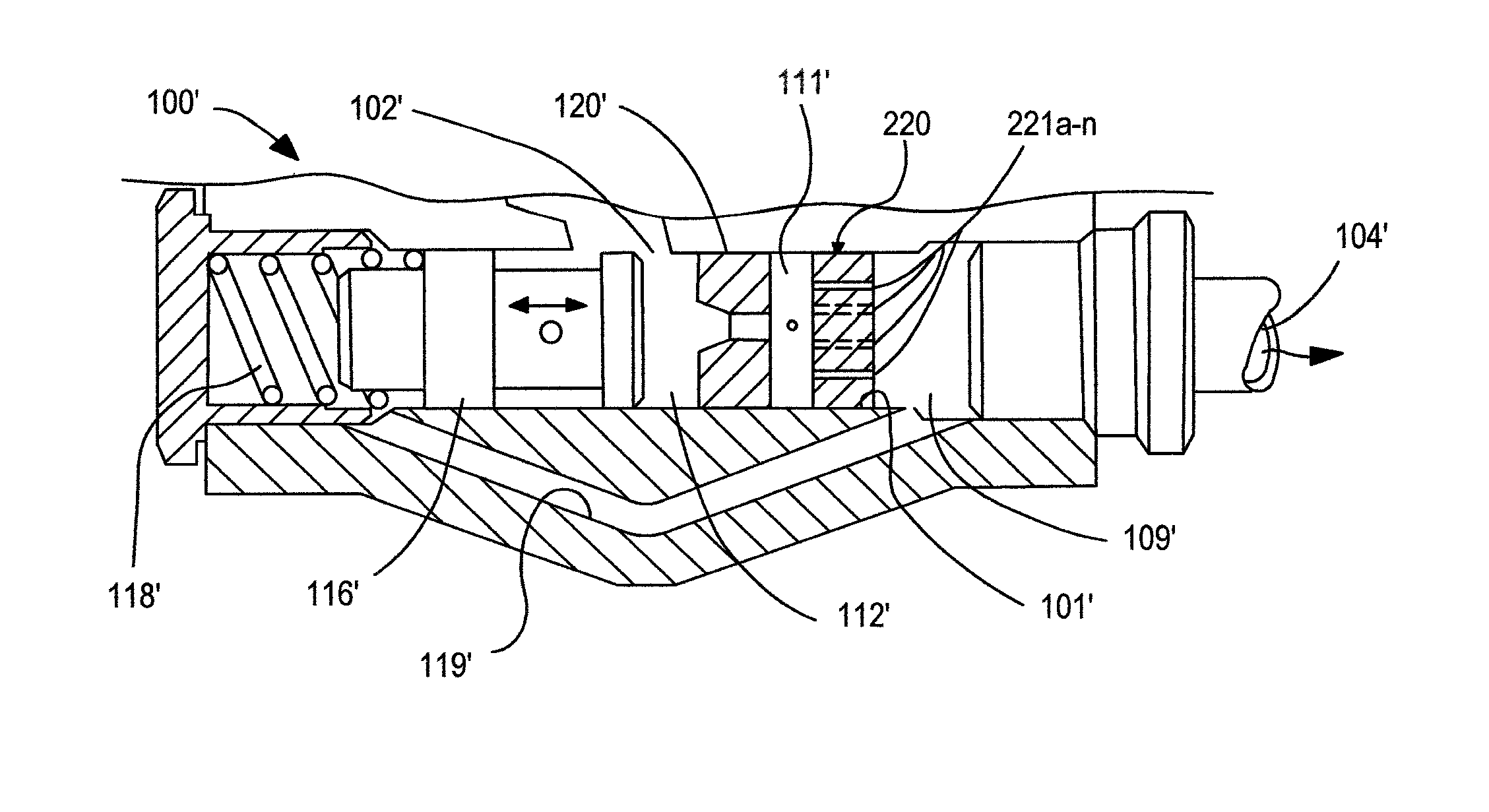
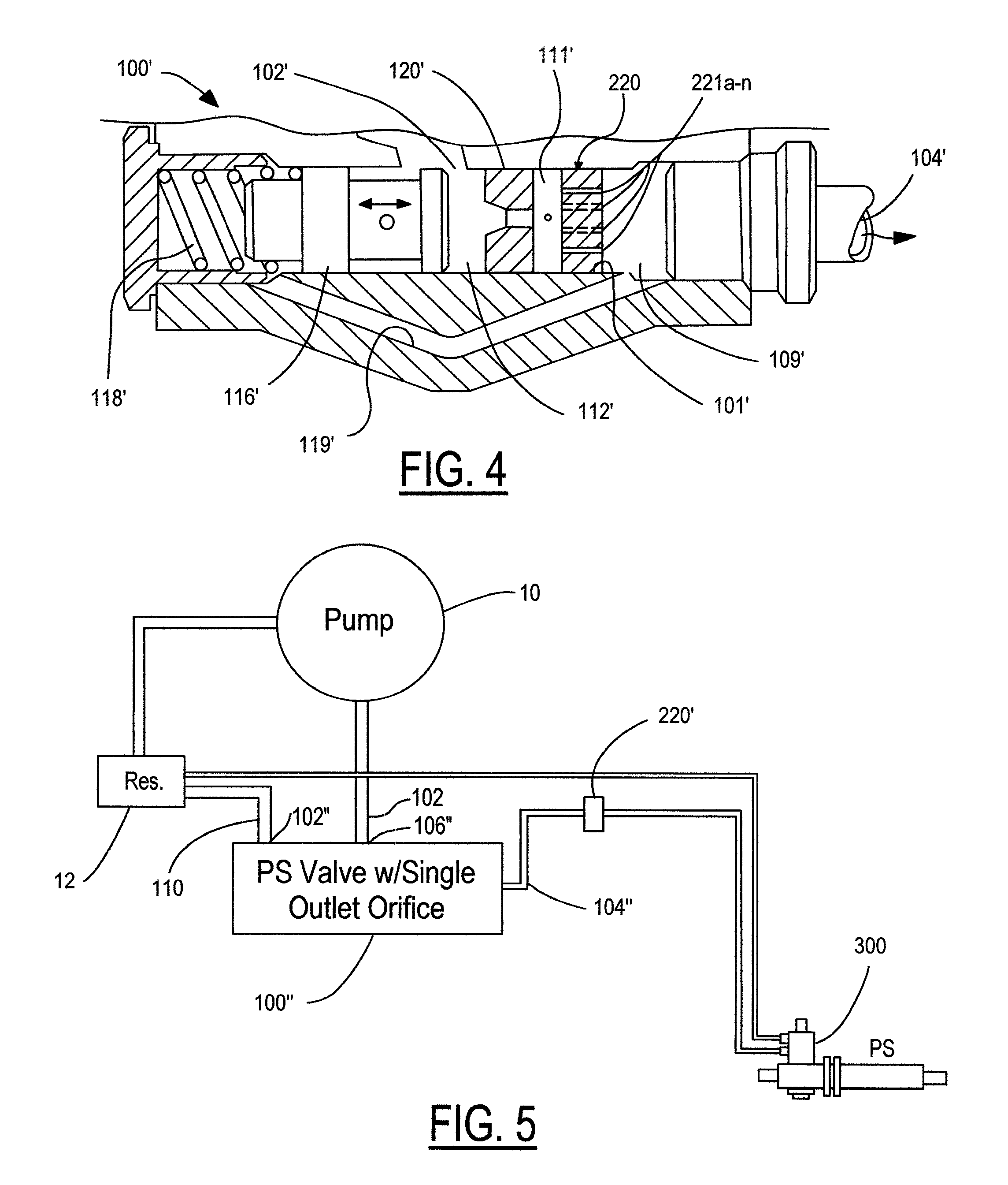
[0030]In FIG. 4, the invention is shown in which the multiple passage orifice element 220 is placed downstream of a single passage outlet orifice element 120′ in the bore 101′ of a hydro-mechanical flow control device 100′. Multiple passage orifice element 220 is separated by a space 111′ from single passage outlet orifice element 120′ and prior to the opening to the feedback passage 119′. Multiple passage orifice element 220 is tight fitted in bore 101′ to require that all fluid flowing into outlet passage 109′ passes through the passages 221a-221n. The two orifice elements 120′ and 220, in series, act to provide the increased shear forces to high viscosity fluid flow at very low temperatures. During normal operation when the fluid is at its working temperatures, the multiple passage orifice element 220 does not interfere with the pressure control function of the single orifice element 120′.

second embodiment

[0031]In FIG. 5, the present invention is shown. The engine driven pump 10 has its low pressure input 13 connected to a reservoir 12 and its high pressure output 107 connected to a hydro-mechanical flow control device 100″ (also referred to as a “power steering valve”). The bypass port 102″ is connected to reservoir 12 via a hose 110. In this embodiment, the multiple passage orifice element 220′ is placed downstream of a single passage outlet orifice element of hydro-mechanical flow control device 100″. Here, the multiple passage orifice element 220′ is located in the outlet hose that leads from the hydro-mechanical flow control device 100″ to the steering assist valve 300.

[0032]The second embodiment illustrates how the present invention allows one the flexibility of locating the multiple passage orifice element anywhere downstream of the single passage outlet orifice element of a hydro-mechanical flow control device and before the power steering assist valve, while achieving the ob...


PUM


Abstract

An apparatus for preventing noise from occurring due to cavitation in a power steering pump during low temperature start-up includes the addition of a multi-passage orifice element for adding wetted surface resistance to high viscous fluid flow downstream from a single passage outlet orifice element of a fluid flow control device and upstream of an associated steering gear or steering assist valve.

Description

BACKGROUND[0001]1. Field of the Invention[0002]This invention relates to the field of controlling the fluid flow rate for hydraulic pumps, especially for automotive power steering pumps, and more specifically to the area of eliminating cavitation that results from pumping high viscosity fluid at extremely low temperatures.[0003]2. Description of the Prior Art[0004]At very low temperatures extending to near −40° F., the viscosity or resistance to flow of fluid used in automotive power steering systems increases by about 8000 times as compared to its viscosity at 275° F. At such low temperatures, the fluid flows like thick, heavy syrup.[0005]Conventionally, power steering systems have a reservoir located remotely, or at least separate, from the hydraulic pump that pressurizes the system. The reservoir is usually placed in a relatively uncongested region of the engine compartment in comparison to the region surrounding the pump and drive belt sheave, by which the pump is driven from an...

Claims


Application Information

Patent Timeline
Patent Type & Authority Patents(United States)
IPC IPC(8): F04B49/00F15B11/08F16D31/02F15B21/047
CPCB62D5/062F15B21/047
Inventor JOSHI, SAMIRBISHOP, LEONARD F.MYERS, DOUGLAS C.
Owner FORD GLOBAL TECH LLC
Why Eureka
Try Eureka