Debris minimization and improved spatial resolution in pulsed laser ablation of materials

a laser ablation and material technology, applied in the field of modifying structures by laser, can solve the problems of reducing the optical transmission of the underlying quartz surface, affecting the ablation effect, so as to reduce the concentration of ablation products and reduce the laser pulse energy

Inactive Publication Date: 2011-08-09
GLOBALFOUNDRIES INC
View PDF17 Cites 12 Cited by
  • Summary
  • Abstract
  • Description
  • Claims
  • Application Information

AI Technical Summary

Benefits of technology

[0008]The present invention is directed to a method and an apparatus for minimizing the deposition of debris onto a sample being ablated. In one embodiment the method includes the steps of: 1) reducing a laser pulse energy to approximately a threshold level for ablation; and 2) ablating a region of the sample using a multitude of laser pulses, each pulse being sufficiently separated in time to reduce a concentration of ablation products in a gas phase. In another embodiment an apparatus is used to ablate a region of a sample with a laser beam. The apparatus comprises: 1) a source providing a pulsed laser beam of a certain energy, the source focusing the laser beam on the sample to ablate a region of the sample; and 2) a device for providing a flowing fluid over the region being ablated to remove the ablation products.

Problems solved by technology

During the manufacture of photomasks and / or integrated circuits, undesirable structures or parts of structures require removal or modification.
This damage may be the result of splatter or haze created during the ablation of the material.
Several disadvantages are Ga implanting as the undesired material is removed which significantly reduces the optical transmission of the underlying quartz surface.
Also, the underlying quartz is almost always damaged by erosion and pitting.
Thus, thermal ablation from nanosecond pulses is not acceptable for repairing features having a size below 1 micron.

Method used


Image

  • Debris minimization and improved spatial resolution in pulsed laser ablation of materials
  • Debris minimization and improved spatial resolution in pulsed laser ablation of materials
  • Debris minimization and improved spatial resolution in pulsed laser ablation of materials

Examples


Embodiment Construction

)

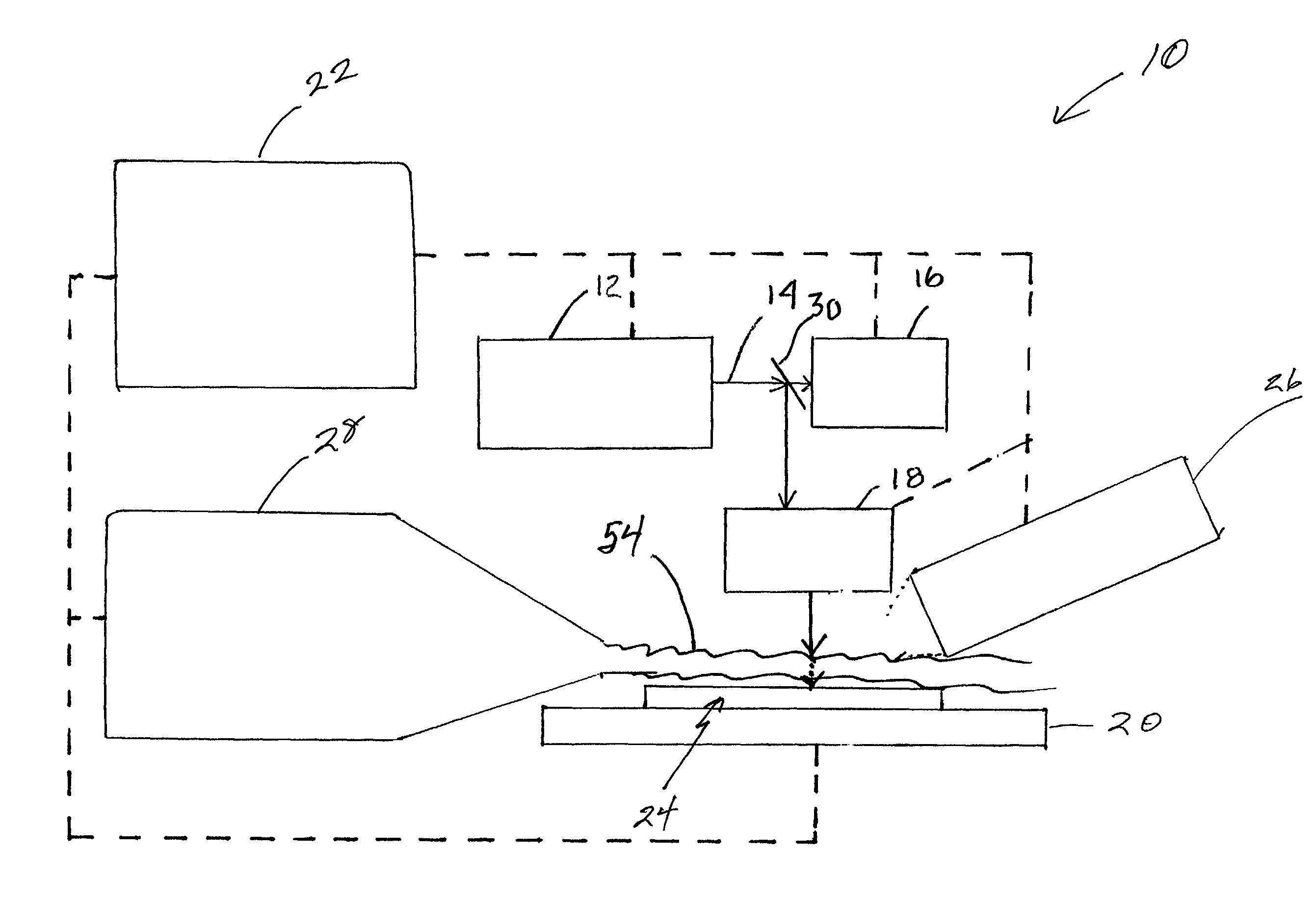
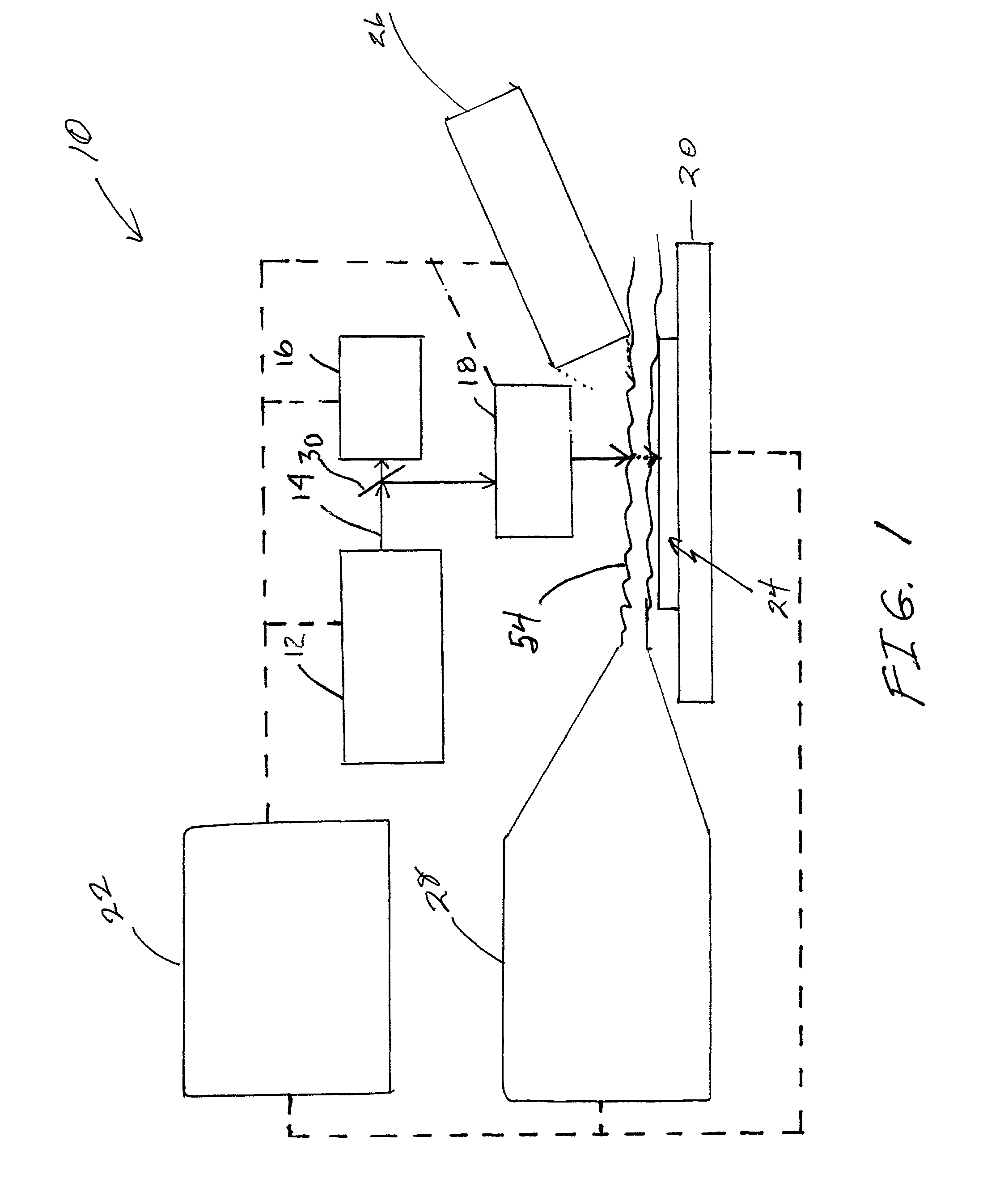
[0020]Referring to FIG. 1, there is shown a laser ablation system 10 incorporating features of the present invention. Although the present invention will be described with reference to the embodiments shown in the drawings, it should be understood that the present invention can be embodied in many alternate forms of embodiments. In addition, any suitable size, shape or type of elements or materials can be used.

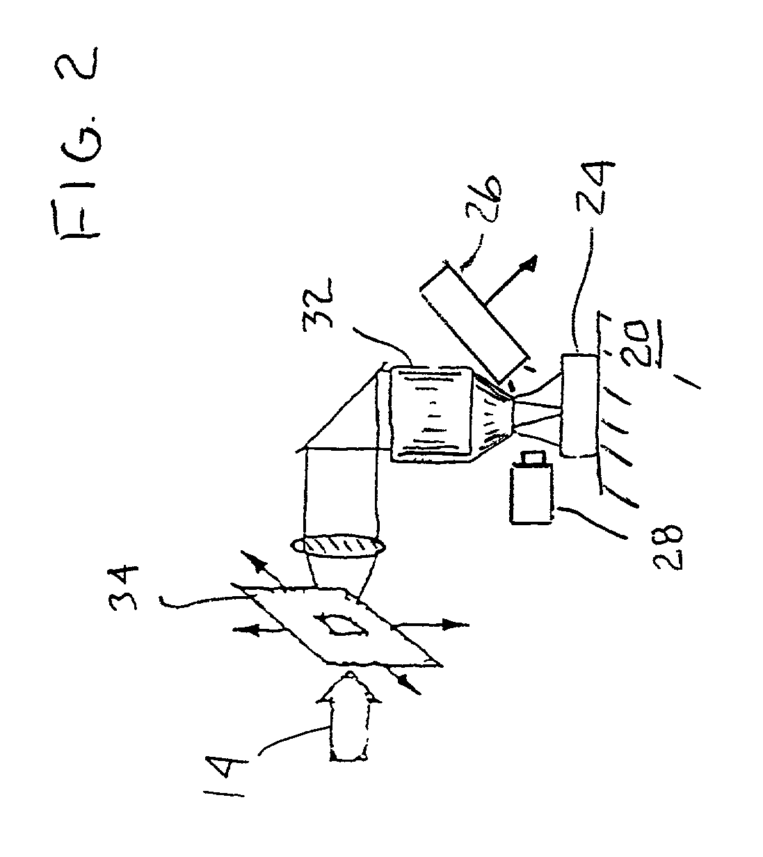
[0021]As shown in FIG. 1, the laser ablation system 10 removes material from a sample 24, FIG. 2, by means a laser 12. The laser 12 outputs a laser beam 14 having an energy minimally above the threshold of ablation for the sample 24 to minimize debris formed. Further, the debris formed may also be removed by a flowing fluid 36, FIG. 3, such as a gas or a liquid, and further the flowing liquid may have the refractive index matched to a high resolution immersion objective lens material and or the material being removed to enhance spatial resolution.

[0022]The refractive index ma...


PUM

PropertyMeasurementUnit
wavelengthaaaaaaaaaa
sizeaaaaaaaaaa
energyaaaaaaaaaa

Abstract

A method and an apparatus of minimizing the deposition of debris onto a sample being ablated. The method comprising the steps of: 1) reducing a laser pulse energy to approximately a threshold level for ablation; and 2) ablating a region of the sample using a multitude of laser pulses, each pulse being sufficiently separated in time to reduce a concentration of ablation products in a gas phase. An apparatus for ablating a region of a sample with a laser beam. The apparatus comprises: 1) a source providing a pulsed laser beam of a certain energy, the source focusing the laser beam on the sample to ablate a region of the sample; and 2) a device for providing a flowing fluid over the region being ablated to remove the ablation products.

Description

BACKGROUND OF THE INVENTION[0001]1. Field of the Invention[0002]The present invention relates to modifying structures by a laser, and, more particularly, to removing material from photomasks and / or integrated circuits by the use of a pulsed laser.[0003]2. Brief Description of Related Developments[0004]During the manufacture of photomasks and / or integrated circuits, undesirable structures or parts of structures require removal or modification. Several techniques have been used to accomplish these objects in the past.[0005]Almost all photomasks manufactured and especially, leading edge photomasks require the correction of defects that normally form as a result of excess chromium (Cr), for example, on the underlying substrate such as quartz (SiO2). The removal of such defects must not damage adjacent structures with the material removed by a laser, for example. This damage may be the result of splatter or haze created during the ablation of the material.[0006]Several techniques have be...

Claims


Application Information

Patent Timeline
Patent Type & Authority Patents(United States)
IPC IPC(8): B23K26/00B23K26/073B23K26/16G03F1/82
CPCB23K26/032B23K26/0635B23K26/0656B23K26/0732B23K26/1405B23K26/1417B23K26/147B23K26/1476B23K26/16B23K26/365B23K26/4015G03F1/82B23K2201/42B41M5/24B23K26/142B23K26/0624B23K26/066B23K26/146B23K26/40B23K26/361B23K2103/50B23K2101/42
Inventor HAIGHT, RICHARD A.LONGO, PETER P.WAGNER, ALFRED
Owner GLOBALFOUNDRIES INC
Why Eureka
Try Eureka