

Water-resistant optical cable and manufacturing method
a manufacturing method and optical cable technology, applied in the field of water-resistant optical cables and manufacturing methods, can solve the problems of unsatisfactory water-blocking action exerted by oil, unsatisfactory optical cables and the methods for manufacturing the same proposed by the above reported prior art, and achieve the effect of increasing transmission capacity and high quality
- Summary
- Abstract
- Description
- Claims
- Application Information
AI Technical Summary
Benefits of technology
Problems solved by technology
Method used
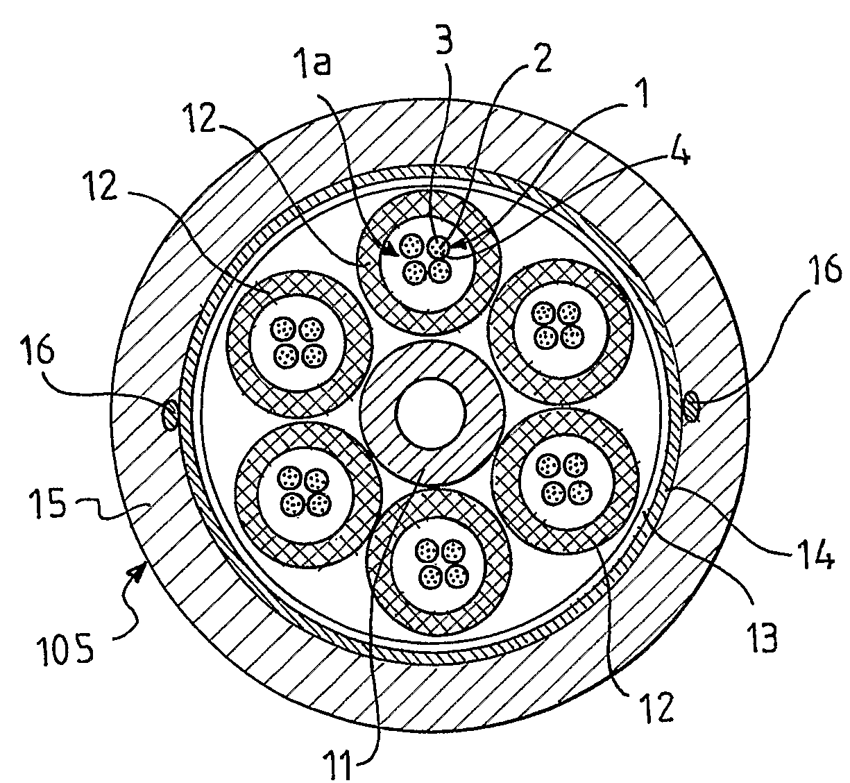
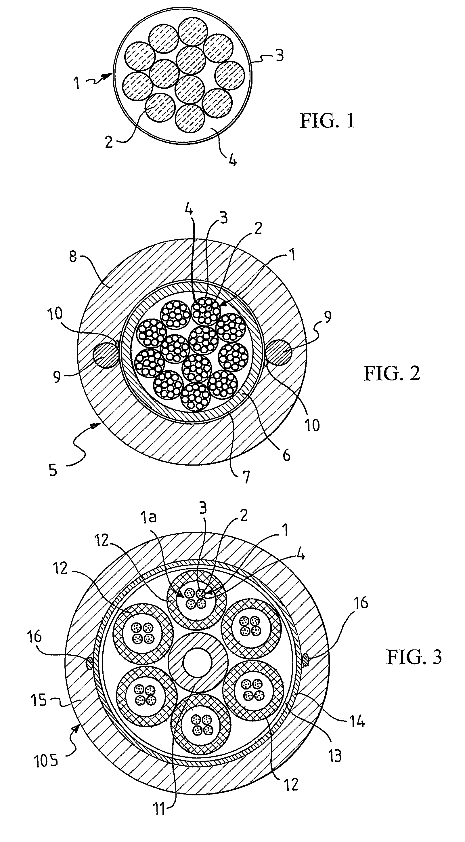
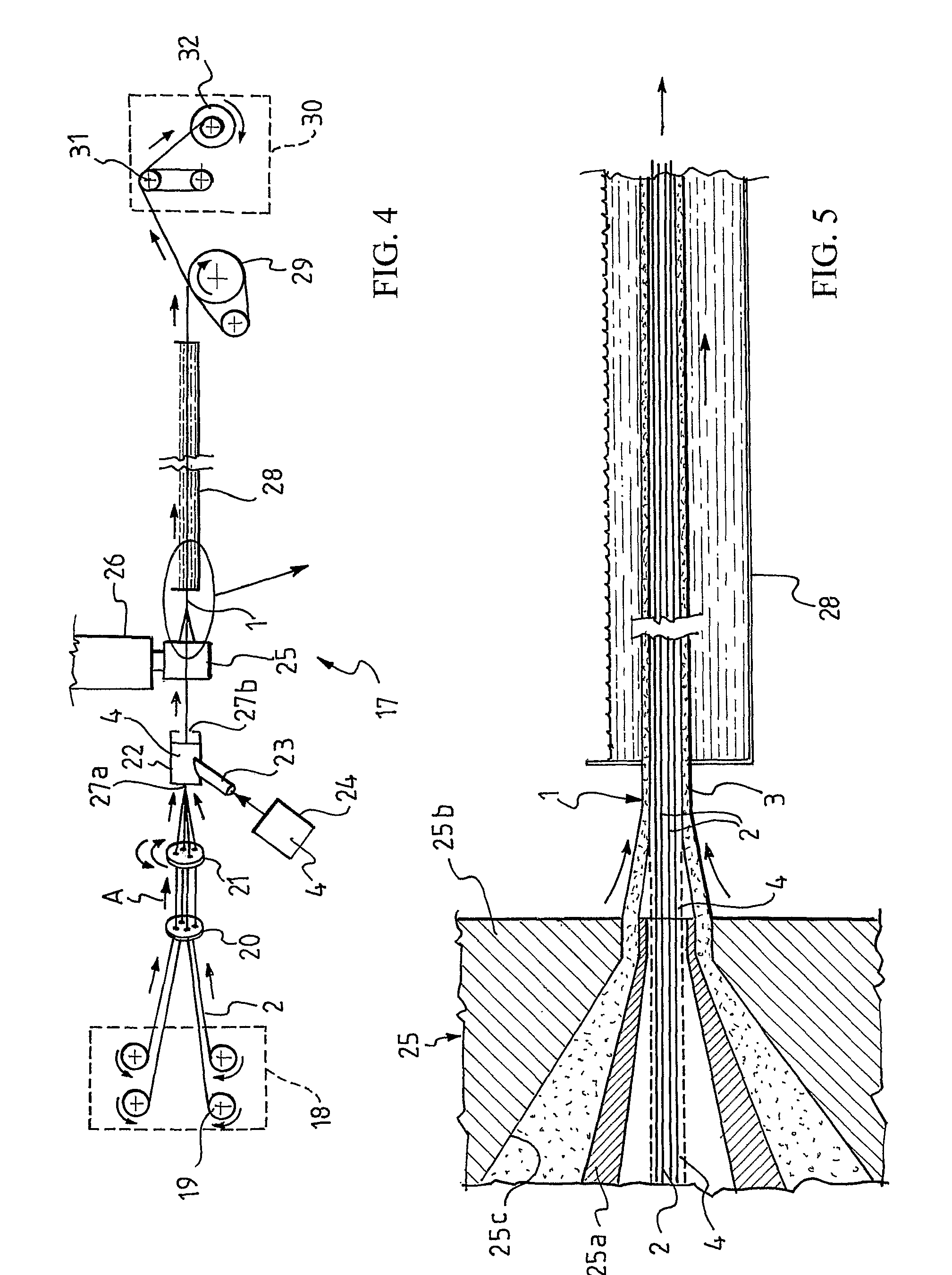
Image

Examples
example 1
Invention
[0199]A filling compound was prepared by mixing silicone oil having a viscosity of 5000 mPa·s at 20° C. (Wacker® AK 5000, available from Wacker-Chemie GmbH, München, Germany) and silica in a ratio of 19 / 1 by weight. The silica was made of a combination of fumed silica (CAB-O-SIL® H-5 having a B.E.T. surface area of 300 m2 / g, available from Cabot Corporation, Boston, Mass.) and of hydrophobic fumed silica treated with dimethyldichlorosilane (e.g. CAB-O-SIL® TS-610) in a ratio of 2 / 3 by weight.
[0200]The viscosity of the filling compound at a shear rate of 10 s−1 and at a temperature of 100° C. was measured by means of the above-mentioned rotational stress control rheometer Bohlin CVO 120, by applying a constant shear rate of 10 s−1, for 60 s, at a constant temperature of 100° C., and by measuring the viscosity after such 60 s. Before each viscosity measurement, in order to minimize undesired macroscopic segregation effects, a manual homogenization of the samples was performed...
example 2
Invention
[0204]A filling compound was prepared by mixing a silicone oil having a viscosity of 5000 mPa·s at 20° C. (Wacker AK 5000, available from Wacker-Chemie GmbH, München, Germany) and silica in a ratio of 13 / 1 by weight. The silica was made of a combination of fumed silica (CAB-O-SIL® H-5 having a B.E.T. surface area of 300 m2 / g, available from Cabot Corporation, Boston, Mass.) and of hydrophobic fumed silica treated with dimethyldichlorosilane (e.g. CAB-O-SIL® TS-610) in a ratio of 5 / 2.2 by weight.
[0205]The viscosity of the filling compound and the cross-over value were determined as described in Example 1: the obtained results are reported in Table I and in Table II, respectively.
example 3
Comparative Example
[0206]A silicone oil Wacker®AK 6000 having a viscosity of 6000 mPa·s at 20° C. (available from Wacker®-Chemie GmbH, München, Germany) was used as filling compound.
[0207]Such filling compound has a Newtonian rheological behavior, whereby its viscosity is independent of the shear rate.
[0208]The viscosity of the filling compound was determined as described in Example 1: the obtained result is reported in Table I.
PUM
| Property | Measurement | Unit |
|---|---|---|
| temperature | aaaaa | aaaaa |
| viscosity | aaaaa | aaaaa |
| viscosity | aaaaa | aaaaa |
Abstract
Description
Claims
Application Information