Fiber optic particle motion sensor system

a motion sensor and fiber optic technology, applied in the direction of optical elements, acceleration measurement using interia forces, instruments, etc., can solve the problems of high cost of sensors, high labor intensity, and high cost of legacy electronic versions of sensors, and achieve the effect of easy demodulation and performance level

Active Publication Date: 2011-08-16
AVALON SCI
View PDF8 Cites 34 Cited by
  • Summary
  • Abstract
  • Description
  • Claims
  • Application Information

AI Technical Summary

Benefits of technology

[0008]The present invention provides a fiber optic sensing system with a level of performance several orders of magnitude higher than is otherwise achievable using prior art technologies. The system combines an FBG sensor packaged as a ‘particle motion sensor,’ such that acceleration, acoustic velocity, or displacement (vibration) cause a corresponding shift in the center wavelength of the FBG reflection (or transmission) spectrum, coupled to a high speed interferometric interrogator, through an unbalanced fiber interferometer. The unbalanced interferometer functions to translate the FBG wavelength shift into a phase shift, which is easily demodulated by the interrogator, i.e., the wavelength shift of an FBG sensor is detected by utilizing the inherent wavelength dependence of an unbalanced fiber interferometer.

Problems solved by technology

Recently, the use of fiber optic sensors has become more prevalent for sensing applications, particularly in those applications where the sensors must be placed in harsh environments, which seriously affects the performance / reliability of the associated electronics.
Historically such sensors have been more costly than the legacy electronic versions because they are difficult to manufacture, require complicated and expensive equipment for even limited automated assembly, and involve significant amounts of skilled touch labor to produce.
Although fiber Bragg grating (FBG) accelerometers are currently available, they incorporate spectroscopic interrogation, which limits the sensitivity to about 1 mg.
However, they are expensive and tend to be unstable.

Method used


Image

  • Fiber optic particle motion sensor system
  • Fiber optic particle motion sensor system
  • Fiber optic particle motion sensor system

Examples


Embodiment Construction

[0021]In the following description, for purposes of explanation and not limitation, specific details are set forth in order to provide a thorough understanding of the present invention. However, it will be apparent to one skilled in the art that the present invention may be practiced in other embodiments that depart from these specific details. In other instances, detailed descriptions of well-known methods and devices are omitted so as to not obscure the description of the present invention with unnecessary detail.

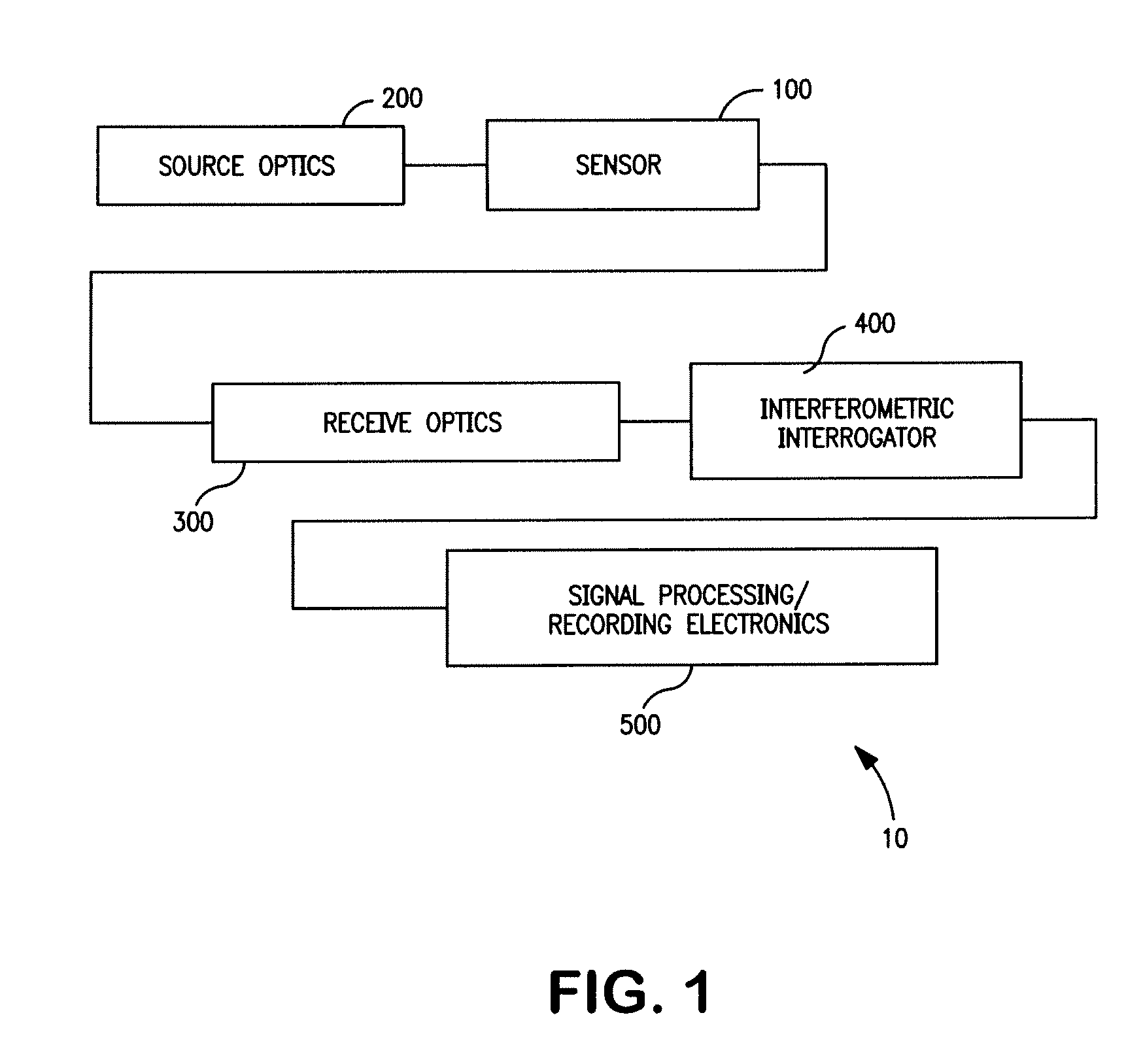
[0022]A particle motion sensing system 10 according to one embodiment of the present invention is shown in FIG. 1. The particle motion sensing system 10 includes a transducer or sensor 100, source optics 200, receive optics 300, an interferometric interrogator 400 and signal processing / recording electronics 500.

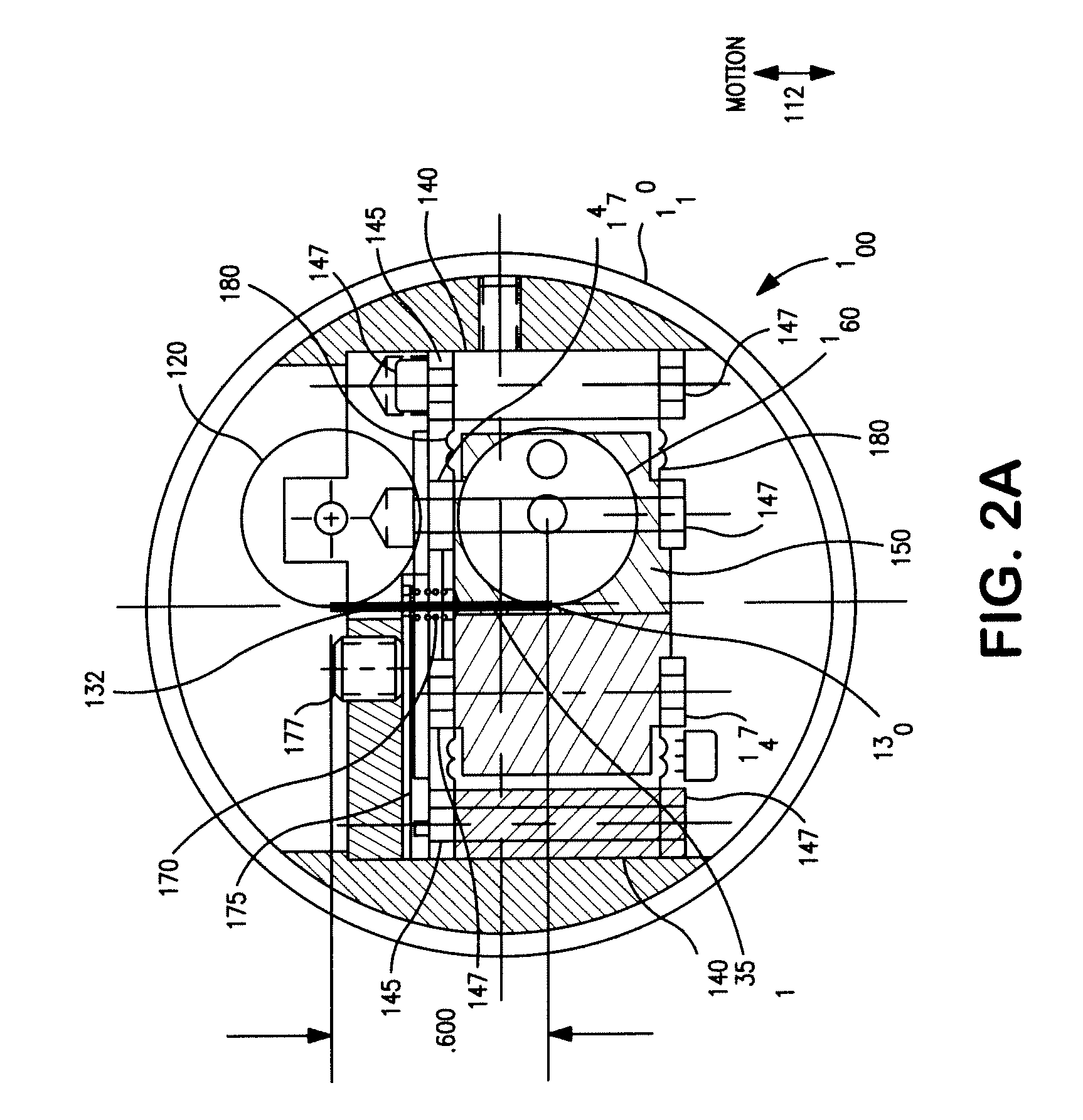
[0023]Although a number of different configurations of the sensor 100 may be employed, FIG. 2A shows an exemplary embodiment for use with narrow band gratings. Sen...


PUM


Abstract

A sensor apparatus combines an optical sensor in which acceleration, acoustic velocity, or displacement (vibration) causes a corresponding shift in the center wavelength of the sensor output, coupled to a high speed interferometric interrogator, through an unbalanced fiber interferometer. The unbalanced interferometer functions to translate optical wavelength shift into phase shift, which is easily demodulated by the interrogator.

Description

CROSS-REFERENCE TO RELATED APPLICATION[0001]This application claims priority of provisional application No. 60 / 999,246 filed Oct. 16, 2007.BACKGROUND OF THE INVENTION[0002]1. Field of the Invention[0003]The invention relates generally to methods and systems for acquiring acceleration and / or velocity data using fiber optic sensors. Specifically, the invention relates to grating sensors with ultra narrow band gratings, combined with interferometric wavelength-to-phase conversion and low noise interferometric interrogation.[0004]2. Background of the Invention[0005]There are many applications that require a device to measure the dynamic acceleration or acoustic velocity signal at a given location. Examples include: the seismic exploration / monitoring of oilfields, seismic monitoring for earthquakes, structural integrity monitoring, and health monitoring of vibrating equipment / machinery acoustic monitoring in marine environments (e.g., SONAR). For decades, such monitoring has been almost ...

Claims


Application Information

Patent Timeline
Patent Type & Authority Patents(United States)
IPC IPC(8): G01B9/02
CPCG01H9/004G01P15/093G02B6/022G02B6/29319G02B6/29349
Inventor ANDERSEN, JAMES K.GOLDNER, ERIC LEELAM, LEOMOREY, WILLIAMBUSH, IRA JEFFREYBAKER, GERALDCHERBETTCHIAN, AGOP
Owner AVALON SCI
Why Eureka
Try Eureka