Apparatus and arrangement for housing voltage conditioning and filtering circuitry components for an electrostatic precipitator

a technology of electrostatic precipitator and housing, which is applied in the direction of transformer/react mounting/support/suspension, electrical supply techniques, electrical apparatus contruction details, etc., can solve the problems of affecting the entire operation and affecting the efficiency of the electrostatic precipitator. , to achieve the effect of simplifying the change of coolant, reducing the amount of excess heat, and discharging excess hea

Inactive Publication Date: 2011-08-16
THE BABCOCK & WILCOX CO
View PDF17 Cites 15 Cited by
  • Summary
  • Abstract
  • Description
  • Claims
  • Application Information

AI Technical Summary

Problems solved by technology

Sparking occurs when the gas that is being treated in the exhaust stack has a localized breakdown so that there is a rapid rise in electrical current with an associated decrease in voltage.
Sparking can cause damage to the internal components of the electrostatic precipitator as well as disrupt the entire operation of the electrostatic precipitator.
Unfortunately, this lower level of average voltage adversely affects the particle collection efficiency of the electrostatic precipitator.
In fact, all of the components together occupy a significant amount of space and consequently impose significant space and footprint requirements for an installation.
Unfortunately, locations in which such electrostatic precipitators and their associated voltage controlling electronics are typically used suffer from a dearth of available installation space.

Method used


Image

  • Apparatus and arrangement for housing voltage conditioning and filtering circuitry components for an electrostatic precipitator
  • Apparatus and arrangement for housing voltage conditioning and filtering circuitry components for an electrostatic precipitator
  • Apparatus and arrangement for housing voltage conditioning and filtering circuitry components for an electrostatic precipitator

Examples


Embodiment Construction

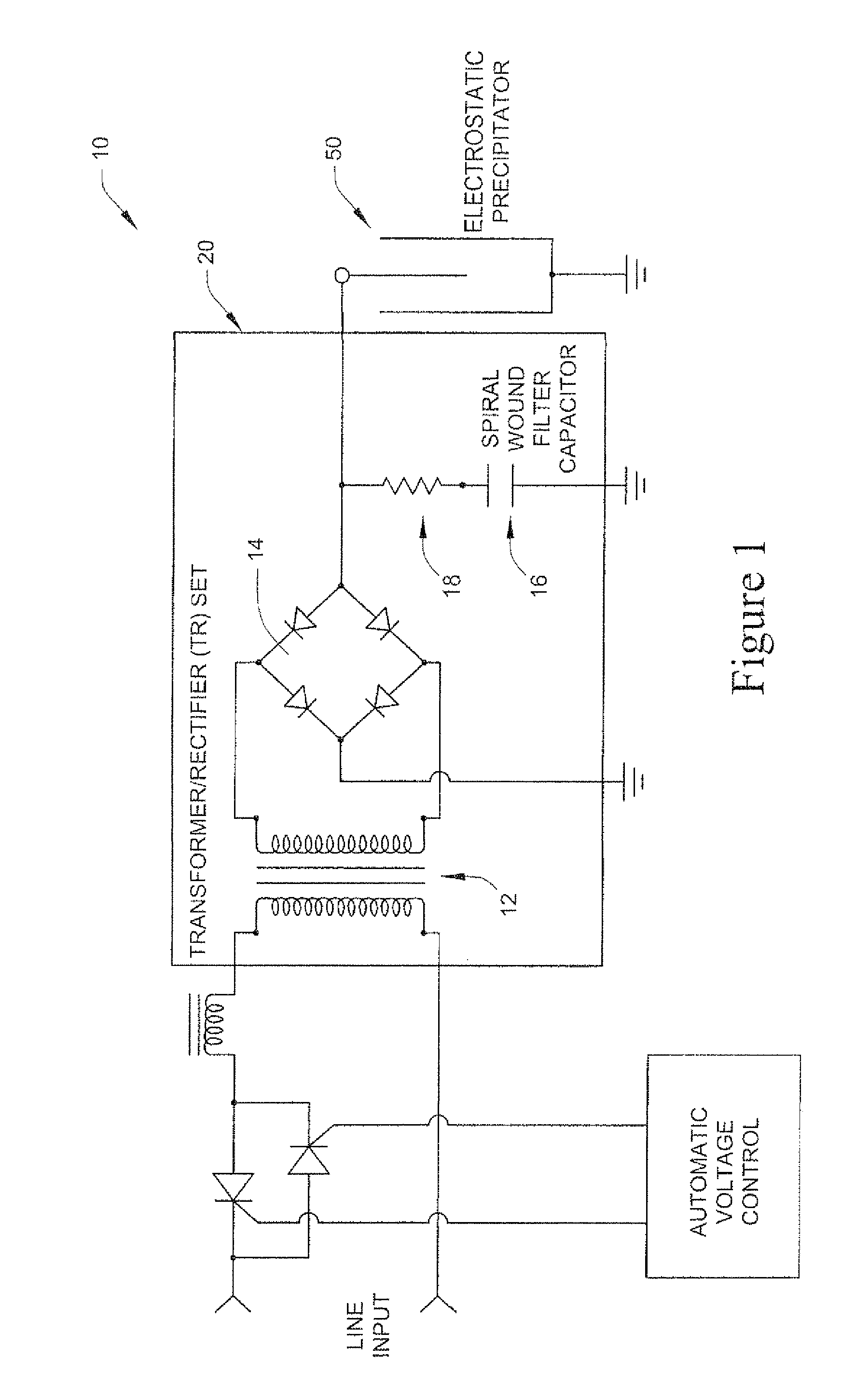
[0022]In FIG. 1, an example schematic circuit diagram of a voltage conditioning and filtering circuit conventionally used for providing a currently-controlled pulsing high-voltage waveform to an electrostatic precipitator device is generally indicated at numeral 10. The voltage control circuit 10 for conditioning and filtering the output voltage waveform to an electrostatic precipitator device 50 includes AC current input controlling SCRs connected to some conventional voltage control circuitry, a Transformer-Rectifier set (12, 14) and an R-C filter network (16, 18) consisting of high-voltage spiral wound filter capacitor 16 and an optional series connected current limiting resistor 18. The output of the series combination of spiral wound capacitor 16 and optional resistor 18 is electrically connected in parallel with electrostatic precipitator device 50, which is placed in an exhaust gas stack outside and away from component housing 20.

[0023]For example, an alternating current volt...


PUM


Abstract

A unitary-enclosure housing apparatus and arrangement for protecting and cooling the high voltage electronic conditioning and filtering circuitry components used for providing a high-voltage waveform to an electrostatic precipitator device includes a hermetically sealed dielectric liquid coolant filled tank / housing having one or more side-mounted hollow-panel type radiator structures for dissipating heat from the coolant. The disclosed unitary-enclosure housing apparatus and the particular arrangement of the internal electronic components results in a relatively external small footprint while containing both the transformer-rectifier (TR) set and high-voltage resistor-capacitor (R-C) filter components associated with a high-voltage electrostatic precipitator device in a single unitary package. The housing apparatus is outfitted with a removable top cover plate and access panel for providing easy access to the TR set and R-C filter components. A coolant drain spigot is also provided on the housing for simplifying the draining and replacement of coolant liquid.

Description

[0001]The subject matter disclosed herein relates to a unitary enclosure housing apparatus for protecting and cooling voltage conditioning and filtering circuitry components conventionally used for providing a current-controlled pulsing high-voltage waveform to an electrostatic precipitator device.BACKGROUND[0002]Some of the primary sources of industrial air pollution today include particulate matter produced from the combustion of fossil fuels, engine exhaust gases, and various chemical processes. An electrostatic precipitator provides an efficient way to eliminate or reduce particulate matter pollution produced during such processes. The electrostatic precipitator generates a strong electrical field that is applied to process combustion gases / products passing out an exhaust stack. Basically, the strong electric field charges any particulate matter discharged along with the combustion gases. These charged particles may then be easily collected electrically before exiting the exhaus...

Claims


Application Information

Patent Timeline
Patent Type & Authority Patents(United States)
IPC IPC(8): H05K7/20
CPCB03C3/68B03C3/82B03C3/86H01F27/025H01F27/12H01F27/40
Inventor JOHNSTON, DAVID FULTONFARMER, TERRY LEWISROBERTS, EASELSTEINHAUR, DAN
Owner THE BABCOCK & WILCOX CO
Why Eureka
Try Eureka