Method of grouting commercial kitchen floors using a two-part reactive epoxy grout

a technology of reactive epoxy and commercial kitchen, which is applied in the field of floor grouting, can solve the problems of ultimate failure of traditional grout products, and achieve the effects of low odor, rapid cure time and rapid cur

Active Publication Date: 2011-08-23
SQUITIERI JOHN
View PDF14 Cites 10 Cited by
  • Summary
  • Abstract
  • Description
  • Claims
  • Application Information

AI Technical Summary

Benefits of technology

[0017]A further object of this invention is to provide a unique process for regrouting commercial kitchen floors with a two-part epoxy grout having a rapid cure, low odor, custom formulated colors and is prepackaged and capable of using static mixer tubes.
[0018]A still further object of this invention is to provide a fast unique regrouting process for commercial floors using a two-part epoxy grout in a prepackaged metering cartridge having a rapid cure time and being easily applied and resistant to deterioration.

Problems solved by technology

These factors will lead to disintegration and ultimately failure with traditional grout products but are withstood by the new system for years with no change in performance.

Method used


Image

  • Method of grouting commercial kitchen floors using a two-part reactive epoxy grout
  • Method of grouting commercial kitchen floors using a two-part reactive epoxy grout
  • Method of grouting commercial kitchen floors using a two-part reactive epoxy grout

Examples


Embodiment Construction

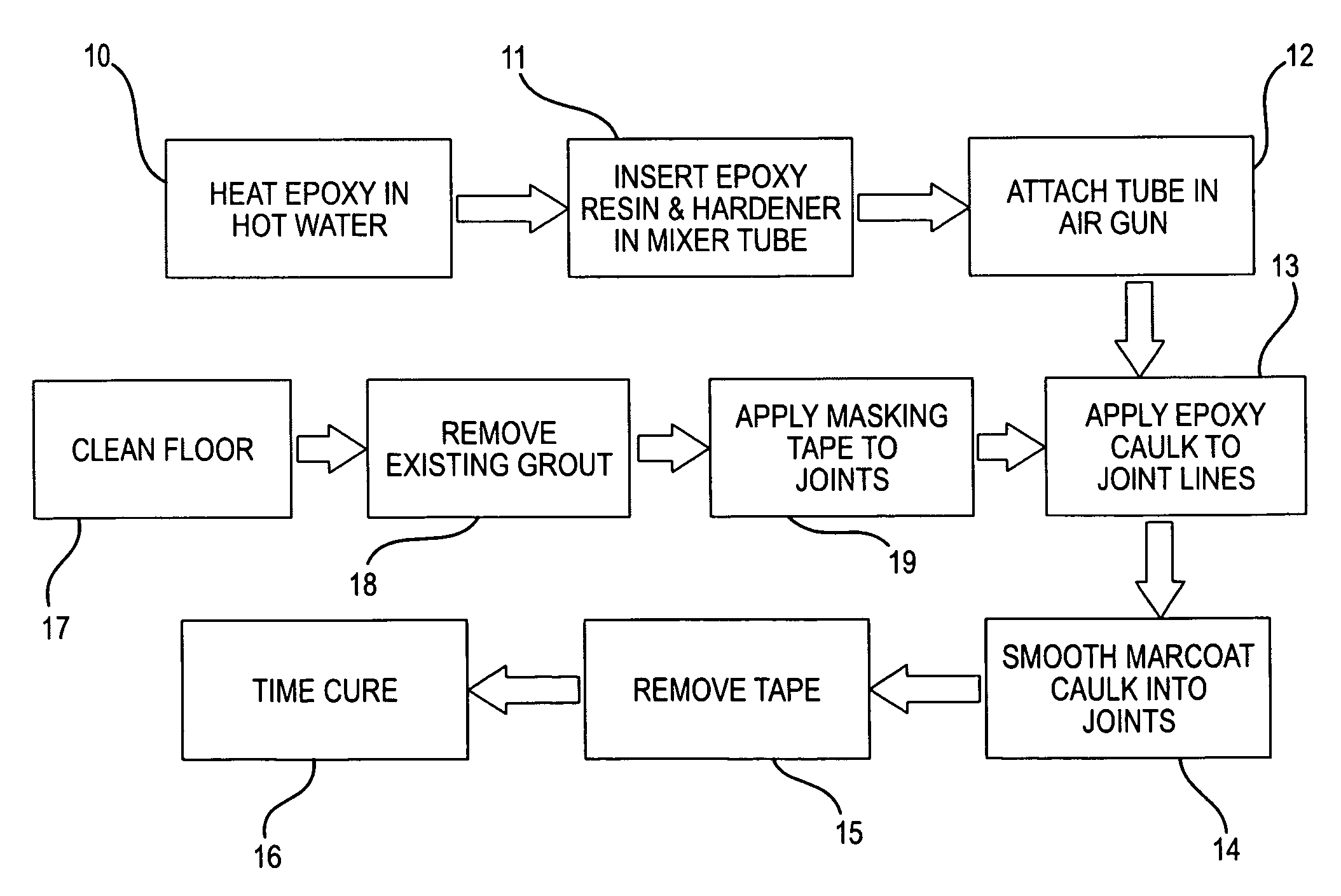
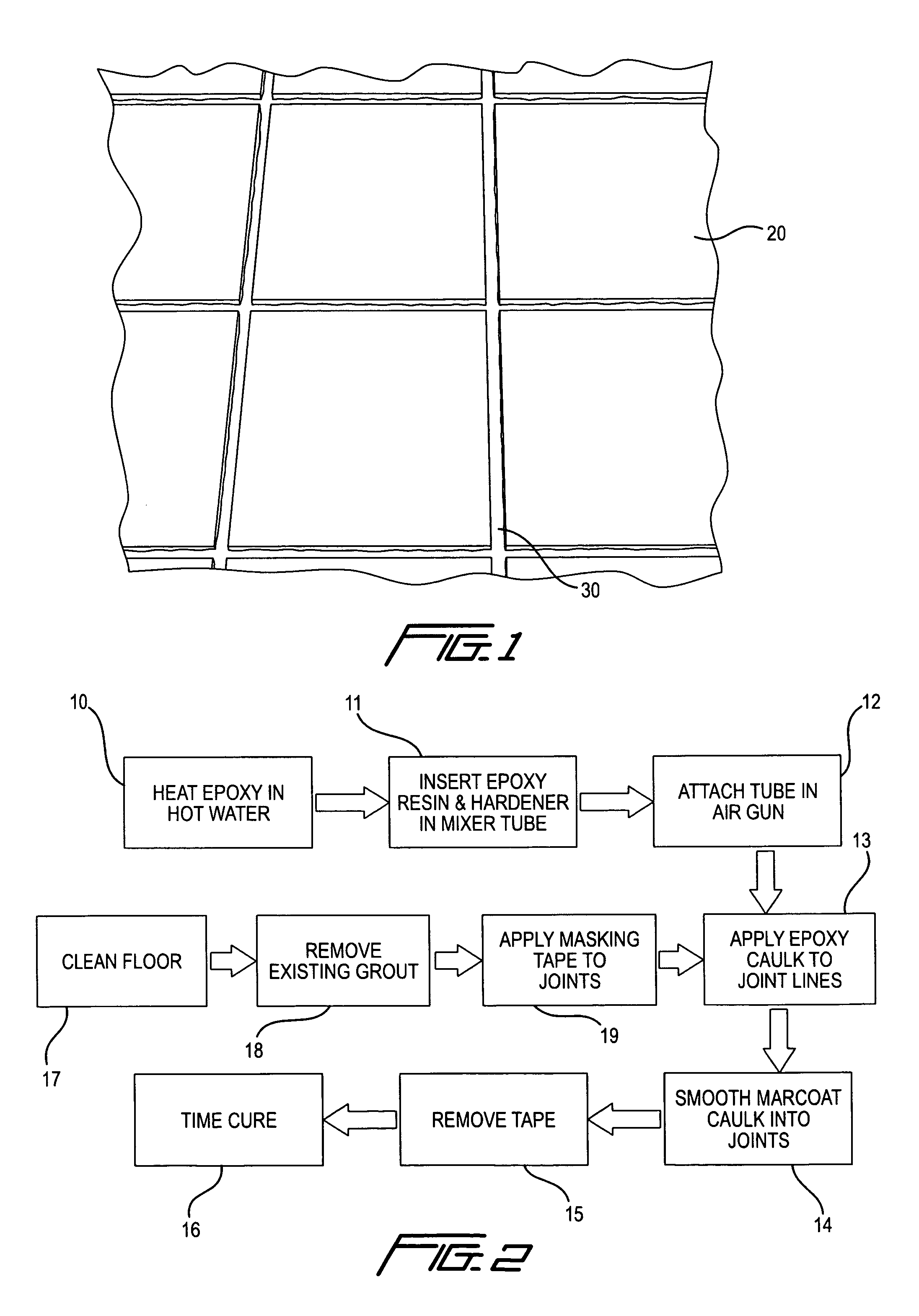
[0026]Referring now to the drawings, FIG. 1 of the drawings depicts tile 20 with deteriorated grout 30 on a floor which is the object of this regrouting process disclosed herein. FIG. 2 discloses the process of this invention which involves steps 1-16.

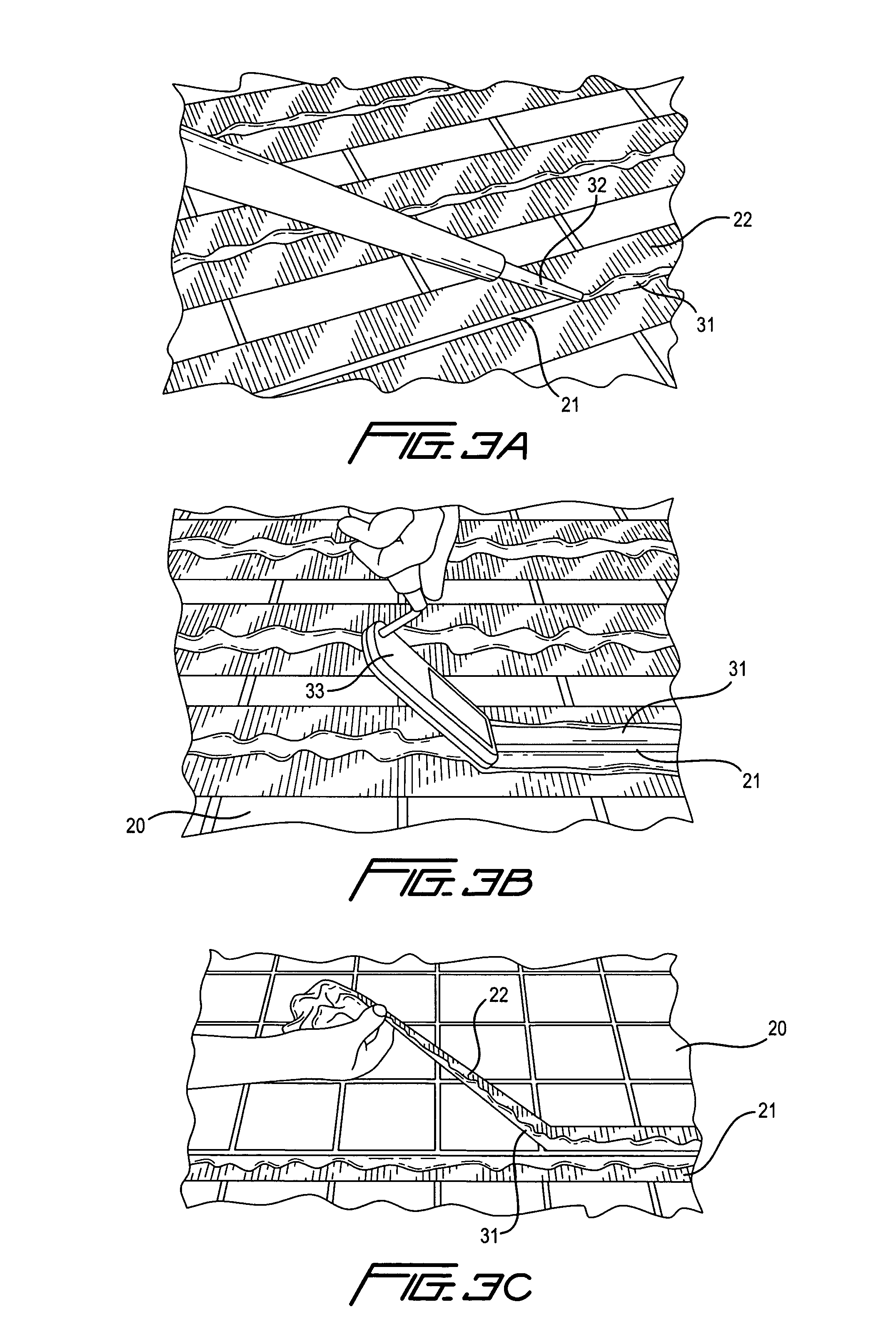
[0027]FIG. 3 depicts step 13 with the dispensing gun 35 applying epoxy grout 31 through a static mixing applicator nozzle p 32 into the joint 21 between the strips of masking tape 22.

[0028]FIG. 3B depicts step 14 wherein the epoxy grout 31 is smoothed into the joint 21 between tiles 20 with a leveling tool 33.

[0029]FIG. 3C depicts step 14 which is the removal of tape 22 from both sides of the joint 21.

[0030]The reactive epoxy based floor grout 31 used in this unique process was especially formulated to be packaged in cartridges 34 and is labeled as Marcoat® floor grout epoxy. This product was developed to have the highest solvent resistance possible to withstand harsh environments, where heavy foot traffic, aggressive cleaning agents i...


PUM

PropertyMeasurementUnit
specific gravitiesaaaaaaaaaa
temperatureaaaaaaaaaa

Abstract

A process for grouting floors using a two-part reactive epoxy grout formulation comprising two distinct components (parts) which can utilize a two-part cartridge for storing, metering and having a means of attaching a static mixer tube to the front of the cartridge for inline mixing of the epoxy components as they are being dispensed directly into the grout joint. The cartridge contains a resin and pre-colored hardener, which maybe heated to accelerate the cure speed in cold environments if necessary, mixed, and applied to an empty grout joint-line by means of a static mixer tube that acts as a mixer-nozzle. Masking tape or other protective material is placed on both sides of the joint-line prior to grouting to prevent epoxy contacting tile faces. The grout is dispensed directly into the grout joint by the applicator gun pressurizing the cartridge pistons to flow epoxy resin and hardener in the correct mix ratio through the static mixing nozzle. A leveling tool is used to even out the dispensed grout into the grout joint and remove excess material before curing. By means of the reactivity of the hardener and resin, which are mixed in the proper stoichiometric ratios, the epoxy will cure in the designed period of time to allow full use within hours after application. A two-part methyl methacrylate grout formulation can be used in grouting new tiled floors or regrouting existing tiled floors with the same procedures as the two part reactive epoxy grout.

Description

CROSS REFERENCE TO RELATED APPLICATIONS[0001]Not applicable.STATEMENT REGARDING FEDERALLY SPONSORED RESEARCH OR DEVELOPMENT[0002]Not applicablePARTIES TO A JOINT RESEARCH AGREEMENT[0003]Not applicableBACKGROUND OF THE INVENTION[0004]This invention relates to floor grouting and in particular to a new and improved process for regrouting commercial floors using a two-part reactive epoxy grout including but not limited to: kitchen, bathroom, lobby, food service area floors where high traffic, aggressive chemicals or severe methods are used in daily cleaning.FIELD OF THE INVENTION[0005]A large number of commercial kitchen floors are constructed with commercial tiles including quarry, ceramic, glazed and other durable compositions which have grout joints (spaces between tiles can vary) to separate the tiles. The grout used to fill these spaces typically is sanded grout for large widths and unsanded for narrower width joints. These grout preparations are mixed with water, and / or have epoxy...

Claims


Application Information

Patent Timeline
Patent Type & Authority Patents(United States)
IPC IPC(8): E04G21/20E04B1/68
CPCC08L63/00E04F21/00E04F21/06E04F21/20
Inventor SQUITIERI, JOHN
Owner SQUITIERI JOHN
Why Eureka
Try Eureka