
Conditioning chamber for metallurgical surface science

a conditioning chamber and surface technology, applied in the field of conditioning chambers, can solve the problems of long process time, high risk of adverse effects during transport to the instrument, and high risk of adverse effects on the condition of the examination chamber uhv

Inactive Publication Date: 2011-08-23
HER MAJESTY THE QUEEN & RIGHT OF CANADA REPRESENTED BY THE MIN OF NATURAL RESOURCES
View PDF7 Cites 9 Cited by
  • Summary
  • Abstract
  • Description
  • Claims
  • Application Information

AI Technical Summary

Benefits of technology

The present invention provides a conditioning chamber device for metallurgical samples that can be attached to an ultra high vacuum examination instrument. The device is designed to reduce the sample to a high vacuum pressure and prepare it for surface analysis. It includes a vacuum pump, a sample retaining means, a fracturing means, a drying means, and a transporting means. The device can be used with various commercially available examination instruments and is sealed to maintain vacuum and prevent contamination. The technical effects of this invention include improved surface analysis of metallurgical samples and efficient attachment to ultra high vacuum examination instruments.

Problems solved by technology

Such preparation typically involves one or both of two important stages, comprising (1) drying and (2) fracturing, each of which presents problems.
There are problems arising from the use of either of these two principal known methods of drying samples for analysis.
In relation to the first method, where a sample is dried in an inert atmosphere not directly connected to the examination instrument, there are risks of adverse effects during transport to the instrument, including from air exposure.
However, in relation to the second method, i.e. where a sample is not dried in a remote location, but in a forechamber to the instrument, or in the examination chamber itself, although the air exposure risk is reduced or removed, there are two important disadvantages.
Firstly, there is a risk of adverse effect on the UHV conditions of the examination chamber when the sample is moved into that chamber; and secondly, there is the problem that arises from the length of time required for preparation of such samples in the forechamber.
Although a typical forechamber is designed to be pumped down to the desired vacuum condition in a relatively short period, of approximately twenty minutes, the process is of necessity substantially longer, often many hours, for proper preparation of metallurgical samples.
While such samples are in the forechamber, or the examination chamber itself, the examination chamber cannot be accessed for other work, and valuable instrument time is thus lost.
In the second stage of sample preparation for surface science research, i.e. the fracturing of the sample to obtain a suitable surface for analysis, the methods currently in use also raise problems.
Further problems arise in relation to the fracturing method itself.
Typically, current methods of fracturing involve a high energy impact, for example impact by the use of a hammer and chisel in a UHV chamber, after freezing of the sample to an extremely low temperature, generally below 75 K. However, if this method is used for a brittle material, the entire sample can be destroyed.
If instead fracturing is performed in an inert gas in a location which is remote from the examination instrument, there is a serious risk of contamination during transfer to that instrument, the risk being increased by the more reactive nature of the surfaces which have been exposed by fracture.
Further limiting factors at this stage include the shape and size of samples.

Method used


Image

  • Conditioning chamber for metallurgical surface science
  • Conditioning chamber for metallurgical surface science
  • Conditioning chamber for metallurgical surface science

Examples


Embodiment Construction

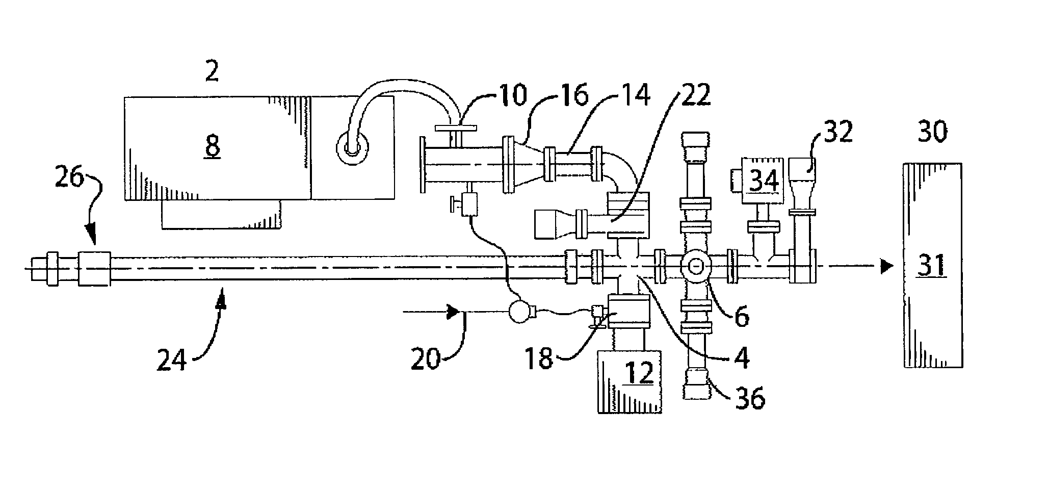
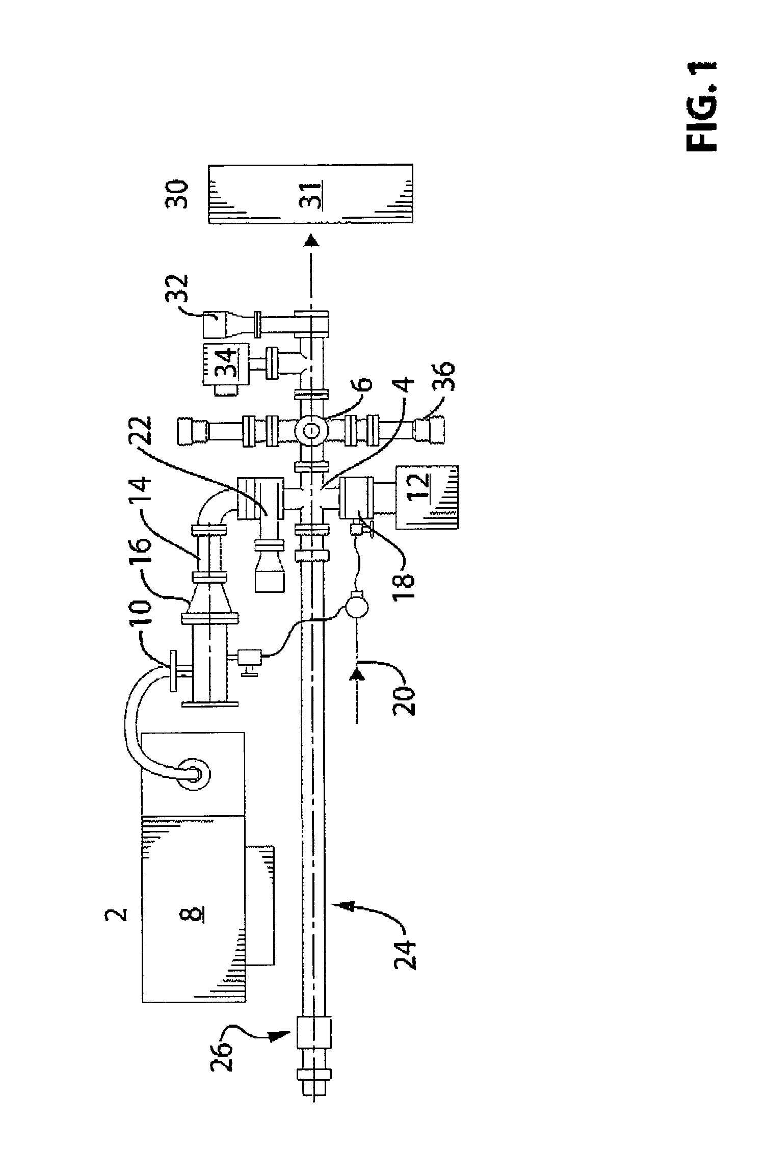
[0044]Referring to FIG. 1, a conditioning chamber device 2 comprises a housing 4, enclosing a chamber 6 which can be brought to an ultra high vacuum (UHV) condition, at or below 10−7 Torr. To achieve this condition, a low vacuum roughing pump 8, a turbomolecular pump 10 and an ion pump 12 are provided which are operable in sequence. The pumps 8, 10 and 12 are connected to the chamber 6 by suitable known linkage components (not specifically identified). As shown in FIG. 1, the first two pumps 8 and 10 are located so as to be connected to the chamber 6 by a first gate valve 22, and the third pump 12 is located so as to be connected to the chamber 6 at a second location, shown in FIG. 1 as adjacent to an up-to-air valve 18, and on the opposite side of the chamber 6 from the connection of the first two pumps 8 and 10. However, any suitable arrangement of the pumps 8, 10 and 12 can be selected such that the pumps can be operated and controlled effectively. Inert gas connection lines 20 f...


PUM

PropertyMeasurementUnit
pressureaaaaaaaaaa
pressureaaaaaaaaaa
temperatureaaaaaaaaaa

Abstract

The present invention provides a conditioning chamber device and a conditioning method for metallurgical samples which can be directly connected to an instrument having an examination chamber operable in an ultra high vacuum (UHV) condition at a selected pressure below 10−7 Torr. The conditioning chamber comprises at least one vacuum pump means to reduce the conditioning chamber to the selected UHV condition corresponding to the selected pressure of the examination chamber; sample retaining means; at least one fracturing means to prepare an analysis surface on the sample; sample drying means for slow drying the sample in the selected UHV condition; a sealable outlet constructed and arranged to be operatively connected to the inlet of the examination chamber; and transporting means to transport the sample after surface preparation through a connecting means into the examination chamber without leaving the selected ultra high vacuum condition.

Description

[0001]This is a Continuation-in-part of U.S. patent application Ser. No. 11 / 115,274, filed Apr. 27, 2005, which is a continuation-in-part of U.S. patent application Ser. No. 10 / 259,747, filed Sep. 30, 2002.FIELD OF THE INVENTION[0002]This invention relates to conditioning chambers for preparation of metallurgical samples for examination and analysis.BACKGROUND OF THE INVENTION[0003]Metallurgical processing for surface science research typically involves the examination of a sample in a vacuum chamber of an examination instrument, generally in an ultra high vacuum (UHV) condition, which can be defined as a pressure which is below 10−7 Torr, and may be down to 10−9 Torr, or lower. Typically, samples are prepared for such research in separate instruments, before an appropriate sample is introduced to a UHV examination chamber.[0004]Such preparation typically involves one or both of two important stages, comprising (1) drying and (2) fracturing, each of which presents problems.[0005]In ...

Claims


Application Information

Patent Timeline
Patent Type & Authority Patents(United States)
IPC IPC(8): G01N1/00
CPCG01N1/286G01N1/32G01N33/20G01N2001/2873G01N33/204
Inventor PRATT, ALLEN
Owner HER MAJESTY THE QUEEN & RIGHT OF CANADA REPRESENTED BY THE MIN OF NATURAL RESOURCES
Learn More