Half block for multi-level interlocking blocks

a technology of interlocking blocks and half blocks, which is applied in the direction of machine supports, transportation items, furniture parts, etc., can solve the problems of substantial (over 20%) breakage in the actual use of the interlocking block form

Active Publication Date: 2011-08-23
SHAW ANNE
View PDF15 Cites 52 Cited by
  • Summary
  • Abstract
  • Description
  • Claims
  • Application Information

AI Technical Summary

Benefits of technology

[0016]Relative to any edge of a first block, in a horizontal direction across the floor plate and normal to said edge, first, second and third rows of four connectors each are adapted, respectively, to engage and interlock a first, second or third row of cavities underneath a second block. A user is thereby capable to forming a steeper or less steep effective ramp grade when said blocks are connected in an assembly of three or more blocks for use in leveling a recreational vehicle.
[0017]In using an assembly of three said blocks, weight of a single wheel portion of a supported vehicle is transmitted onto a top surface of a topmost block, which in turn transmits that force downward in two directions. A first quantity of the downward force is transmitted across the top platform surface to the outer sidewalls of the blocks. A second quantity of the force is transmitted directly downward onto a underlying set of supports. These supports join the sidewalls by way of the underside flanges so that downward force from the top

Problems solved by technology

It has been found that this form of interlocking block suffers from substantial

Method used


Image

  • Half block for multi-level interlocking blocks
  • Half block for multi-level interlocking blocks
  • Half block for multi-level interlocking blocks

Examples


Embodiment Construction

[0034]The invention is now discussed with reference to the figures.

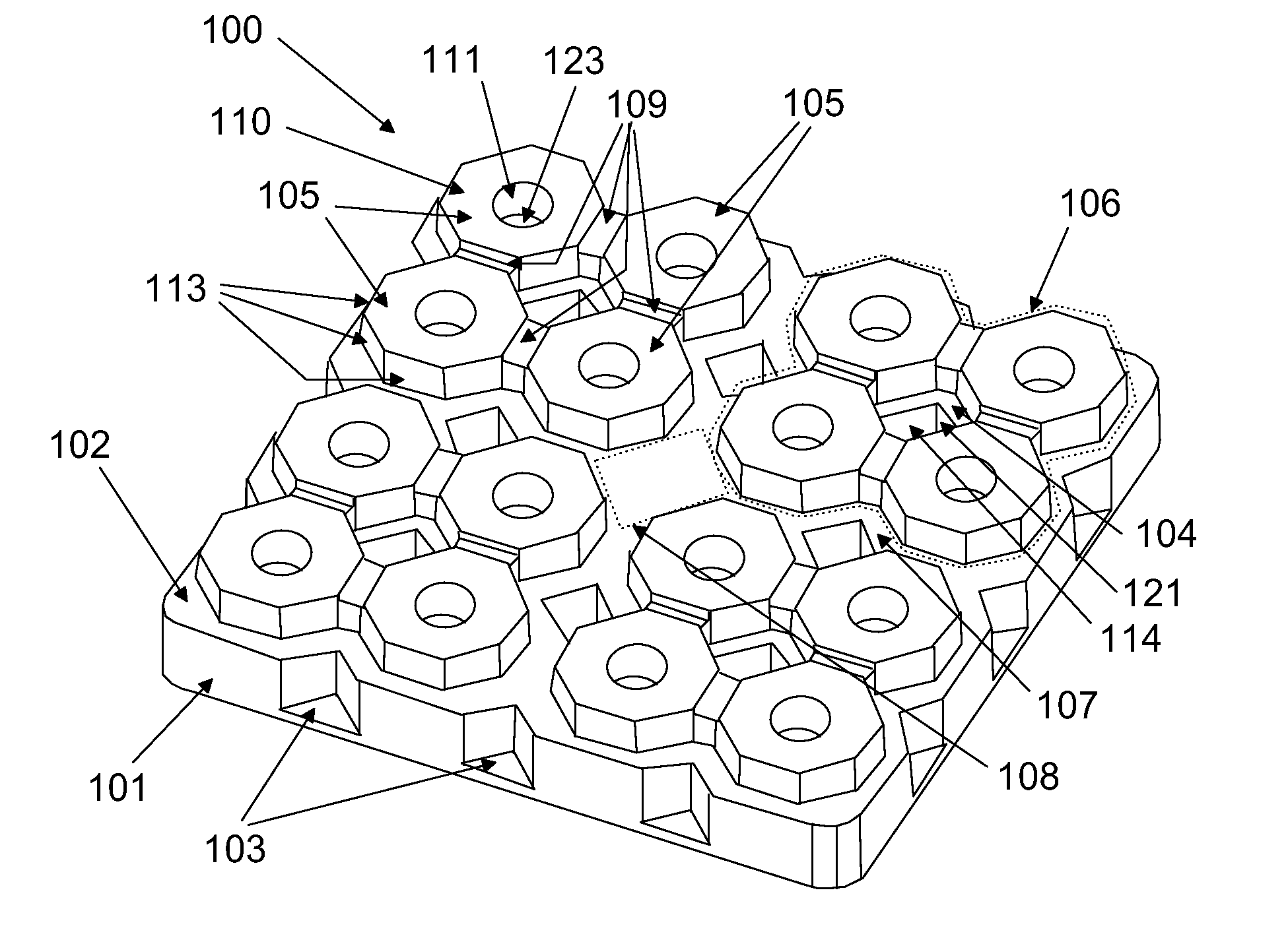
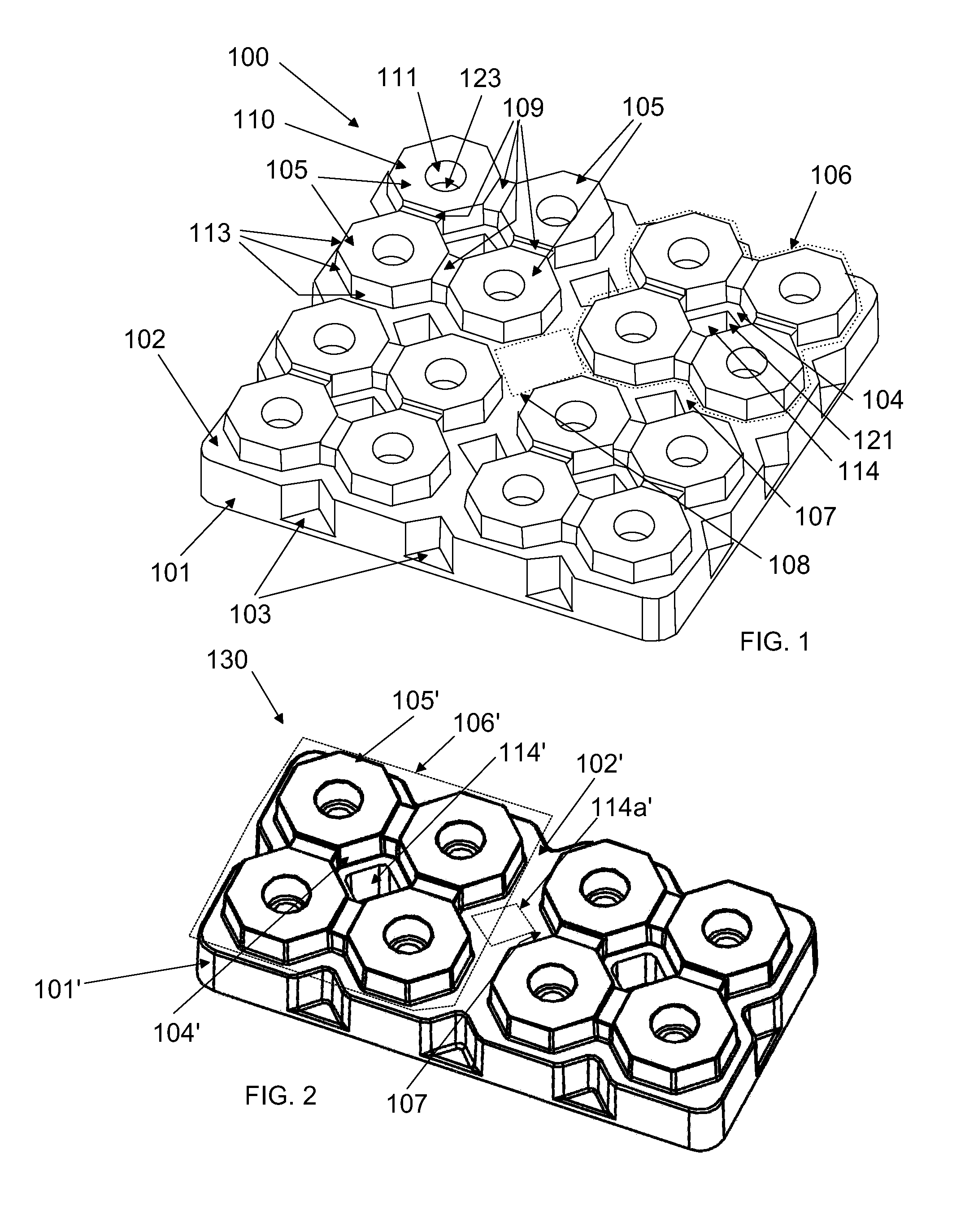
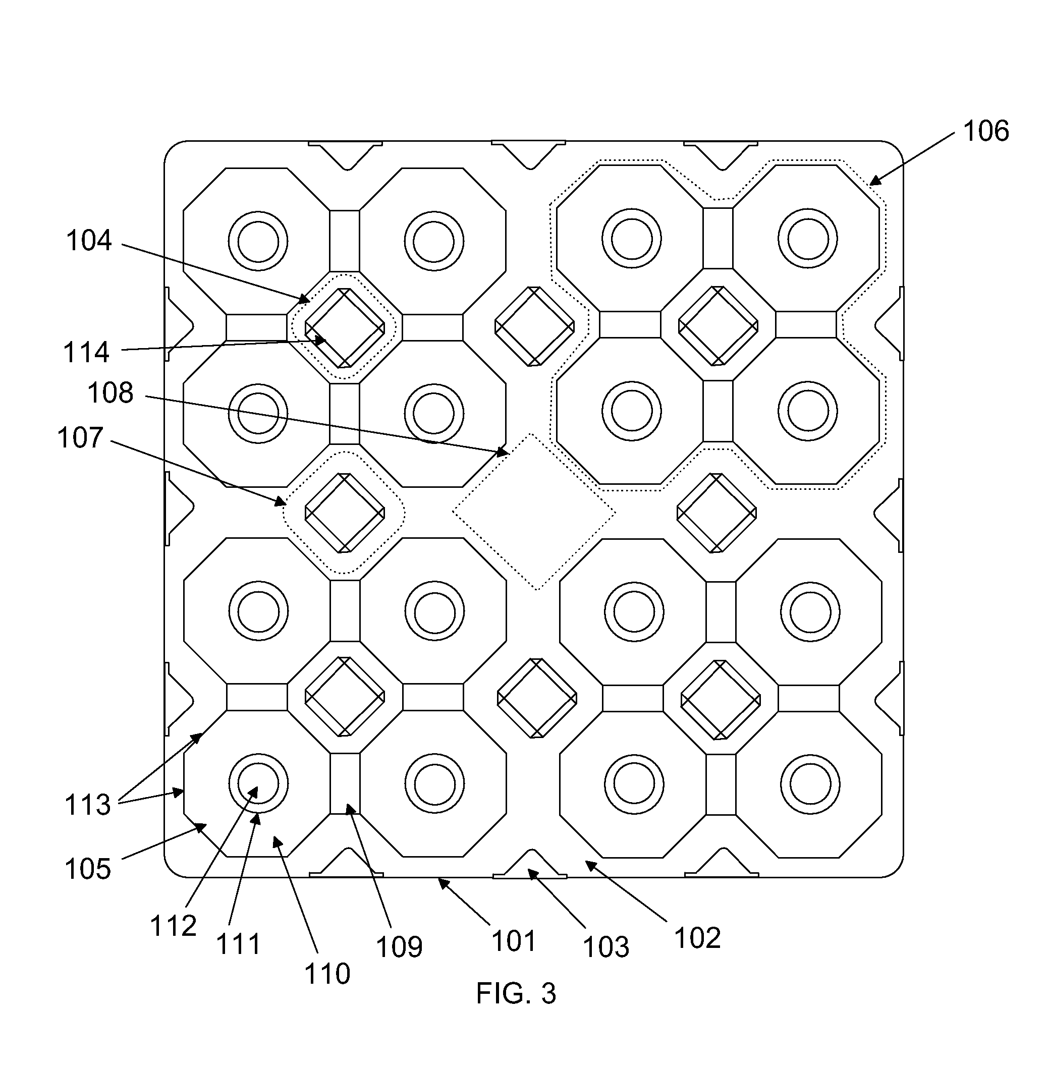
[0035]FIG. 1 shows a base block 100 having sixteen octagonal flat-topped connectors 105 that extend up from the floor plate 102 and comprise a top surface 110 and vertical sidewalls 113. Each connector 105 a central pin bore having cylinder walls 111 and a closed end 112 at the ground level of bore 123 open at the floor plate. Said connectors 105 collectively define eight top peripheral square receiving cavities 104 and 107 and one top central square receiving cavity 108. The sixteen connectors 105 are divided into four connector sets 106 (shown in broken lines), each connector set 106 having four octagonal connectors linked by low projections 109 from the floor plate 102, each set being generally square and arranged at one of four corner portions of the top of the floor plate 102. Opposing and center facing sides 113 of the octagonal connectors 105 are parallel, thereby defining in a central part of the connector se...


PUM


Abstract

The present invention is a unitary piece block formed of polymers (such as polystyrene or other high strength polymer) by a single injection molding step which are assembled into a recreational vehicle leveler. The invention ramp provides four sets of four connectors at a top of a floor plate, which are adapted to interlock in cavity structures formed within a cavity on the underside of the block. Two adjacent blocks are secured together by applying to their top surfaces the securing cavity structure of an underside of a third such block. Such blocks can be stacked in an interlocking manner to reduce storage space.

Description

[0001]This application is a continuation in part of Ser. No. 11 / 728,925 filed Mar. 27, 2007 now U.S. Pat. No. 7,416,166.FIELD OF THE INVENTION[0002]The present invention relates to devices used to level recreational vehicles and travel trailers. More specifically, the present invention relates to plastic interlocking blocks used to level recreational vehicles and travel trailers.BACKGROUND OF THE INVENTION[0003]The prior art describes several forms of interlocking pieces connected so that trucks and recreational vehicles can drive on to them and be leveled at an uneven site.[0004]U.S. Pat. No. D426,933 shows one of a set of at least three interlocking blocks that are set up with two side by side and the third placed on top of halves of the bottom two to lock the three together. It has been found that this form of interlocking block suffers from substantial (over 20%) breakage in actual use with loaded trucks and recreational vehicles. The breakage is due to the particular strains pl...

Claims


Application Information

Patent Timeline
IPC IPC(8): B66F7/24
CPCB60P3/36B66F7/243
Inventor SHAW, ANNE
Owner SHAW ANNE
Why Eureka
Try Eureka