Reducing optical interference in a fluidic device

a fluidic device and optical interference technology, applied in the field of reducing optical interference in fluidic devices, can solve the problems of unsatisfactory elimination of interference and undesired interference signals, and achieve the effect of reducing interference of optical signals

Active Publication Date: 2011-08-30
LABRADOR DIAGNOSTICS LLC
View PDF22 Cites 45 Cited by
  • Summary
  • Abstract
  • Description
  • Claims
  • Application Information

AI Technical Summary

Benefits of technology

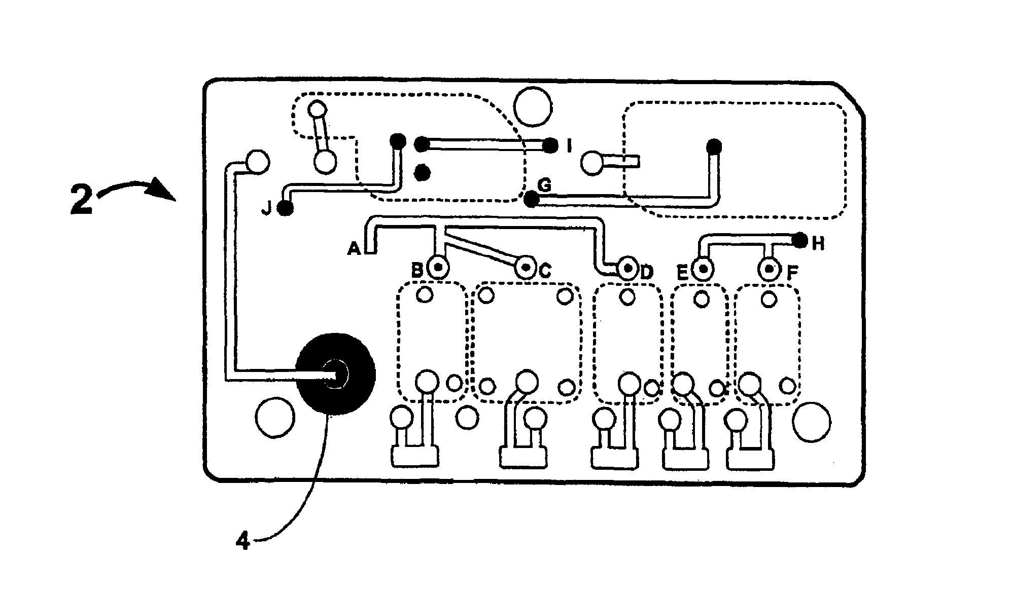
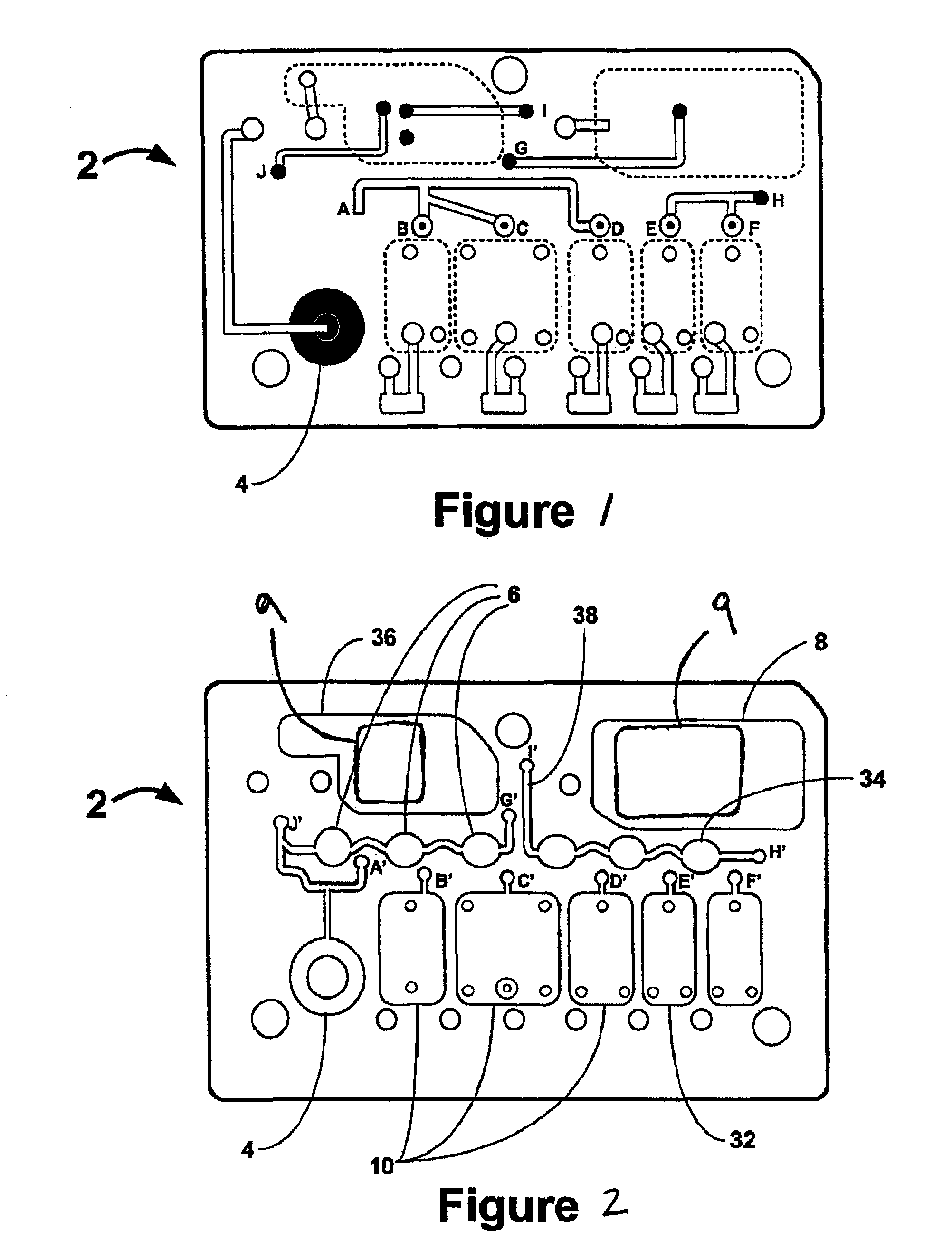
[0006]One aspect of the invention is a fluidic device for detecting an analyte in a sample of bodily fluid. The fluidic device comprises a sample collection unit adapted to provide a sample of bodily fluid into the fluidic device, an assay assembly in fluidic communication with the sample collection unit, wherein the assay assembly is adapted to yield an optical signal indicative of the presence or quantity of the analyte in the sample of bodily fluid, and a quencher assembly in fluidic communication with said assay assembly, wherein the quencher assembly is adapted to reduce interference of the optical signal.

Problems solved by technology

In such assay formats, the excess or unbound enzyme-labeled reagent may react with enzyme substrate, thus creating undesired interfering signals.
These mitigating features, however, may not sufficiently eliminate the interference as light can still travel through transparent elements of the fluidic device and interfere with the signal of interest.

Method used


Image

  • Reducing optical interference in a fluidic device
  • Reducing optical interference in a fluidic device
  • Reducing optical interference in a fluidic device

Examples


example

[0105]A 1×0.5 inch piece of Whatman #32 glass fiber mat (item 10 372 968) was impregnated with 50 uL of 15% w / v 4-amino-1,1-azobenzene-3,4-disulfonic acid (0.4 M) in water then dried in a “dry box”.

[0106]In assays using alkaline-phosphatase (from bovine intestine)-labeled reagents (APase coupled to haptens or to antibodies at concentrations of up to about 10 ug / mL in a dilute tris buffer) and either Lumigen's Lumiphos™ 530, or KPL Phosphoglow™ AP substrates (both are dioxetanes and have an esterified phosphate residue on which the enzyme acts) used as supplied by the vendors (100 uM in dioxetane), the result was about 200 uL of enzyme and 200 uL of substrate in the waste chamber, thus exposed to the adsorbent material.

[0107]After an initial glow rate of 38,550 counts / second (observed by placing the fluidic device in a Molecular Devices M5 luminometer such that the waste chamber was being interrogated), the intensity dropped to about 100 counts / second within a few seconds after addin...


PUM

PropertyMeasurementUnit
volume fractionaaaaaaaaaa
concentrationsaaaaaaaaaa
opticalaaaaaaaaaa

Abstract

This invention is in the field of medical devices. Specifically, the present invention provides portable medical devices that allow real-time detection of analytes from a biological fluid. The methods and devices are particularly useful for providing point-of-care testing for a variety of medical applications. In particular, the medical device reduces interference with an optical signal which is indicative of the presence of an analyte in a bodily sample.

Description

CROSS-REFERENCE[0001]This application is a continuation application of Ser. No. 11 / 549,558, filed Oct. 13, 2006, which is incorporated herein by reference in its entirety and to which application we claim priority under 35 USC §120, which is related to the following co-pending patent application Ser. No. 11 / 389,409, filed Mar. 24, 2006, which is incorporated herein by reference in its entirety.BACKGROUND OF THE INVENTION[0002]The discovery of a vast number of disease biomarkers and the establishment of miniaturized fluidic systems have opened up new avenues to devise methods and systems for the prediction, diagnosis and monitoring of treatment of diseases in a point-of-care setting. Point-of-care testing is particularly desirable because it rapidly delivers results to patients and medical practitioners and enables faster consultation between patients and health care providers. Early diagnosis allows a practitioner to begin treatment sooner and thus avoiding unattended deterioration ...

Claims


Application Information

Patent Timeline
Patent Type & Authority Patents(United States)
IPC IPC(8): G01N33/53B01L99/00
CPCG01N33/542B01L3/5027B01L2200/10Y10T156/10B01L2300/0887B01L2200/14B01L3/00B01L3/502715B01L2200/16B01L2300/069B01L2300/0816B01L2400/0406B01L2400/0487G01N33/483G01N33/533G01N35/08G01N33/52G01N33/5304G01N33/536
Inventor GIBBONS, IANO'CONNELL, MICHAEL
Owner LABRADOR DIAGNOSTICS LLC
Why Eureka
Try Eureka