Planar stage moving apparatus for machine

a technology of moving apparatus and machine, which is applied in the direction of propulsion system, mechanical energy handling, manufacturing tools, etc., can solve the problems of large size and complex structure of the table moving unit, and achieve the effect of improving strength and dynamic characteristics of the planar stage moving apparatus and high precision

Active Publication Date: 2011-08-30
KOREA INST OF MACHINERY & MATERIALS
View PDF13 Cites 13 Cited by
  • Summary
  • Abstract
  • Description
  • Claims
  • Application Information

AI Technical Summary

Benefits of technology

[0013]The present invention has been made in view of the above problems, and the present invention provides a planar stage moving apparatus for a machine that enables reduction of the size of a table transfer system and accurate transfer of a table provided in a machine such as a milling machine by moving the table using an electromagnetic force.
[0022]In particular, since a single table can be both transversely and longitudinally moved, the strength and dynamic characteristics of the planar stage moving apparatus are improved as compared with the case of overlapping two tables of the same area. Further, high precision can be obtained by applying a position sensor such as a linear encoder or a laser displacement measurer. Furthermore, the planar stage moving apparatus can be advantageously applied to a small sized machine tool and a measurement system.

Problems solved by technology

Accordingly, when a table needs to be moved transversely (in the X-axis direction) and longitudinally (in the Y-axis direction) as in a machine tool such as a milling machine, it is necessary for the machine tool to separately include a movement shaft for transverse movement of the table and a movement shaft for longitudinal movement of the table, in which case the structure of a table moving unit is complex and large-sized.

Method used


Image

  • Planar stage moving apparatus for machine
  • Planar stage moving apparatus for machine
  • Planar stage moving apparatus for machine

Examples


Embodiment Construction

[0033]Hereinafter, exemplary embodiments of the present invention will be described in detail with reference to the accompanying drawings so that those skilled in the art can easily carry out the present invention.

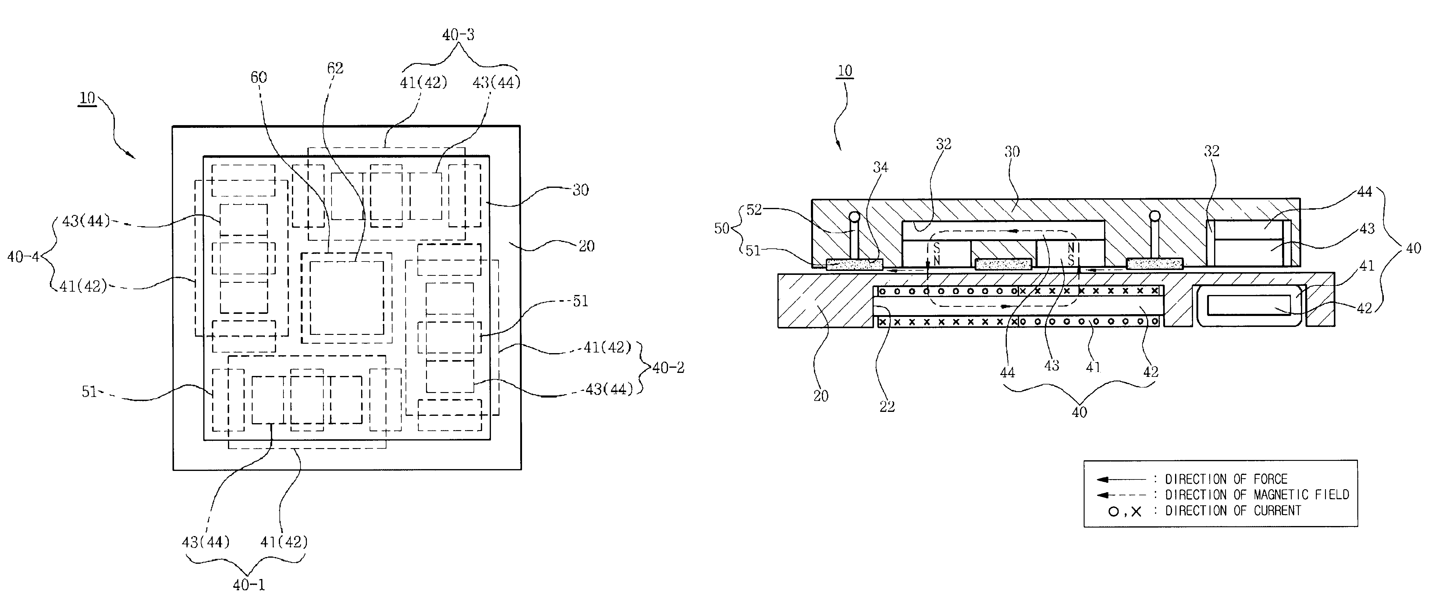
[0034]FIG. 2 is a plan view of a planar stage moving apparatus according to an embodiment of the present invention. FIG. 3 is aside view of the planar stage moving apparatus according to the embodiment of the present invention. FIG. 4 is a view illustrating a unit linear motor applied to the planar stage moving apparatus according to the embodiment of the present invention. FIG. 5 is a plan view of abase according to the embodiment of the present invention. FIG. 6 is a bottom view of a table according to the embodiment of the present invention.

[0035]In a planar stage moving apparatus 10 according to the embodiment of the present invention, a table 30 can be moved on a base 20 in the transverse direction (X-axis direction), the longitudinal direction (Y-axis direction), and...


PUM


Abstract

A planar stage moving apparatus for a machine includes: first to fourth linear motors for applying, between a base, i.e. a fixed body and a table, i.e. a movable body, a movement force to the table, each linear motor including a stator core on which a coil is wound and which is fixed to the base and a mover core to which a permanent magnet is attached and which is fixed to the table; an air bearing unit provided between the base and the table to move the table under the influence of magnet fields when currents are applied to the coils of the linear motors; and a linear encoder installed on one side of the table to measure movement of the table.

Description

BACKGROUND OF THE INVENTION[0001]1. Field of the Invention[0002]The present invention relates generally to a planar stage moving apparatus for a machine and, more particularly, to a planar stage moving apparatus for a machine that enables reduction of the size of a table transfer system and accurate transfer of a table provided in a machine such as a milling machine by moving the table using an electromagnetic force.[0003]2. Description of the Related Art[0004]An apparatus for carrying out a necessary operation while a table positioned on a base is being moved by a separate transfer unit provided for a machine tool or a measurement tool used in the industrial field. In particular, a machine tool such as a milling machine or a wire cutting machine that has a tool fixed to an upper portion of a table to machine a work piece is provided with a table moving unit for moving the table under the control of an NC controller.[0005]A general table moving unit for a machine converts rotational...

Claims


Application Information

Patent Timeline
Patent Type & Authority Patents(United States)
IPC IPC(8): H02K41/02H02K7/08B23Q1/62
CPCB23Q1/62B23Q5/28H02K41/031H02K2201/18H02K7/08H02K11/0026H02K11/22B23Q1/34B23Q7/00
Inventor RO, SEUNG-KOOKPARK, JONG-KWEON
Owner KOREA INST OF MACHINERY & MATERIALS
Why Eureka
Try Eureka