Gate-boosted, variable voltage supply rail amplifier

a supply rail amplifier and variable voltage technology, applied in the field of signal processing, can solve the problems of n greater than 3 not working, class a amplifier is generally inefficient, and class b push-pull pairs often experience cross-over distortion

Active Publication Date: 2011-08-30
CIRRUS LOGIC INC
View PDF5 Cites 15 Cited by
  • Summary
  • Abstract
  • Description
  • Claims
  • Application Information

AI Technical Summary

Problems solved by technology

A class A amplifier is generally inefficient because a class A amplifier is always conducting, even with no input signal.
However, class B push-pull pairs often experience cross-over distortion where the two wave form halves of the push-pull pair join.
Values of N greater than 3 do not work because of limitations in the maximum overdrive voltage VOV.

Method used


Image

  • Gate-boosted, variable voltage supply rail amplifier
  • Gate-boosted, variable voltage supply rail amplifier
  • Gate-boosted, variable voltage supply rail amplifier

Examples


Embodiment Construction

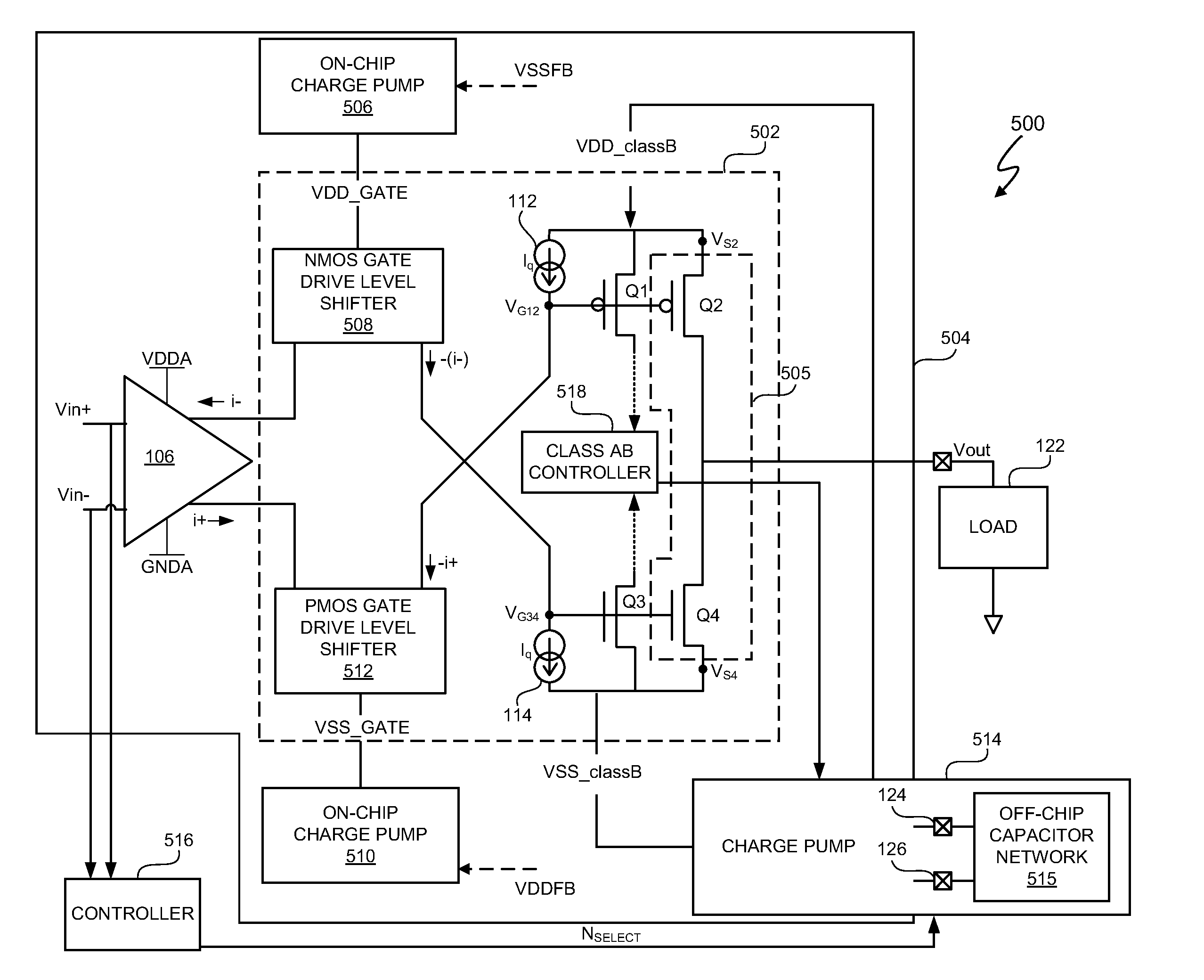
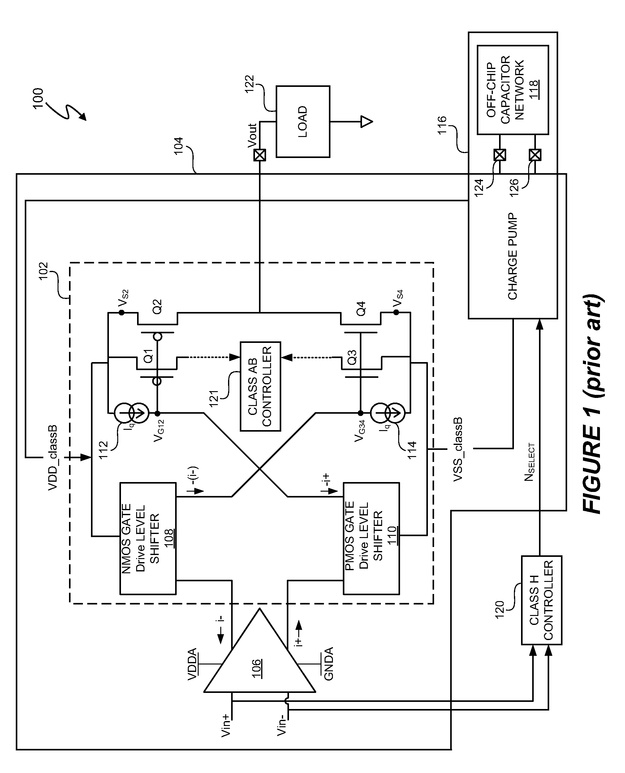
The conventional charge pump with on-chip and off-chip components offers some simplicity in that the conventional charge pump provides gate boost voltages and supply voltage rails. However, the class H control prevents the gate boost voltage from exceeding the supply voltage rails. Thus, the overdrive voltage to the amplifier FETs is limited and significantly restricts the output voltage swing for a given voltage supply rail.

In at least one embodiment, an electronic system includes an amplifier having an on-chip charge pump to provide a gate boost voltage to boost a gate voltage of at least one on-chip field effect transistor (FET) of an output stage of an amplifier. In at least one embodiment, the gate boost voltage boosts the gate voltage higher than the supply voltage rail to increase an overdrive voltage of the on-chip FET. In at least one embodiment, the gate boost voltage boosts the DC bias of an input signal and, thus, generation of gate boost voltage by the on-chip charge pu...


PUM


Abstract

In at least one embodiment, an electronic system includes an amplifier having an on-chip charge pump to provide a gate boost voltage to boost a gate voltage of at least one on-chip field effect transistor (FET) of an output stage of an amplifier. In at least one embodiment, the gate boost voltage boosts the gate voltage higher than the supply voltage rail to increase an overdrive voltage of the on-chip FET. In at least one embodiment, the gate boost voltage boosts the DC bias of an input signal and, thus, generation of gate boost voltage by the on-chip charge pump is signal-independent, i.e. independent of the input signal. Increasing the overdrive voltage increases the efficiency of the amplifier by decreasing the difference between the maximum swing of the output voltage and the voltage supply rails of the at least one on-chip FET relative to conventional designs.

Description

BACKGROUND OF THE INVENTION1. Field of the InventionThe present invention relates in general to the field of signal processing, and more specifically to a system and method that includes a gate-boosted, variable voltage supply rail amplifier.2. Description of the Related ArtElectronic systems often include amplifiers. In general, amplifiers change power and / or amplitude of a signal Amplifiers are used in a large variety of applications, such as audio applications. A variety of amplifier designs exist. Amplifiers are often classified according to the amplifier's input and output properties, such as class A, class B, class AB, and so on. A class A amplifier is generally inefficient because a class A amplifier is always conducting, even with no input signal. Class B amplifiers amplify only one-half of an input signal wave form. Class B amplifiers are often combined into a push-pull pair. However, class B push-pull pairs often experience cross-over distortion where the two wave form hal...

Claims


Application Information

Patent Timeline
Patent Type & Authority Patents(United States)
IPC IPC(8): H03F3/04
CPCH03F1/0216H03F3/3022H03F3/45475H03F2200/513
Inventor ALLEN, DANIEL J.SWANSON, ERIC J.WOODFORD, SCOTT A.
Owner CIRRUS LOGIC INC
Why Eureka
Try Eureka