
Method and apparatus for image processing

a technology of image processing and buffer memory, applied in the field of method and apparatus for image processing, can solve the problems of the number of bits of the error buffer as large as 12, the distribution ratio changes, and the distribution ratio changes, and achieve the effect of decreasing the capacity requirement of the buffer memory

Inactive Publication Date: 2011-08-30
CANON KK
View PDF25 Cites 14 Cited by
  • Summary
  • Abstract
  • Description
  • Claims
  • Application Information

AI Technical Summary

Benefits of technology

[0014]The present invention provides an image processing method and apparatus capable of decreasing the capacity requirements for a buffer memory while compensating for the impact of an arithmetic error at the time of error diffusion.
[0015]According to an aspect of the present invention, input image data is quantized, a quantization error generated by quantization is calculated, and the calculated quantization error is stored in a buffer. The quantization error is diffused on the basis of at least a quantization error of a first pixel, which is stored in the buffer, and the calculated quantization error of a second pixel. In addition, a component that reduces the impact of arithmetic error in error diffusion on subsequent input image data is provided.
[0016]As described above, according to the present invention, since the quantization error is stored in the buffer memory, the buffer memory only needs to have at least a capacity corresponding to the number of bits of the quantization error. Hence, the size of the buffer memory capacity can be reduced. In addition, with inclusion of the reduction component is arranged the influence of arithmetic error can be eliminated. Hence, the image quality of a highlight portion of an image in particular can be increased.

Problems solved by technology

Hence, the number of bits of the error buffer must be as large as 12, which is disadvantageous.
However, since the bit accuracy of the binarization error to be used for error distribution calculation drops, the distribution ratio changes depending on the magnitude of the binarization error.
However, since the bit accuracy of the binarization error to be used for error distribution calculation drops, as in the method disclosed in Japanese Patent Publication No. 07-093682, the distribution ratio changes depending on the magnitude of the binarization error.
If five or more higher bits are stored in the buffer memory to increase the error distribution accuracy, an error is generated due to rounding.
In addition, since the lower bits of the binarization error are added to the input pixel data, the range of the binarization error is extended, resulting in an increase of 1 bit.

Method used


Image

  • Method and apparatus for image processing
  • Method and apparatus for image processing
  • Method and apparatus for image processing

Examples


first embodiment

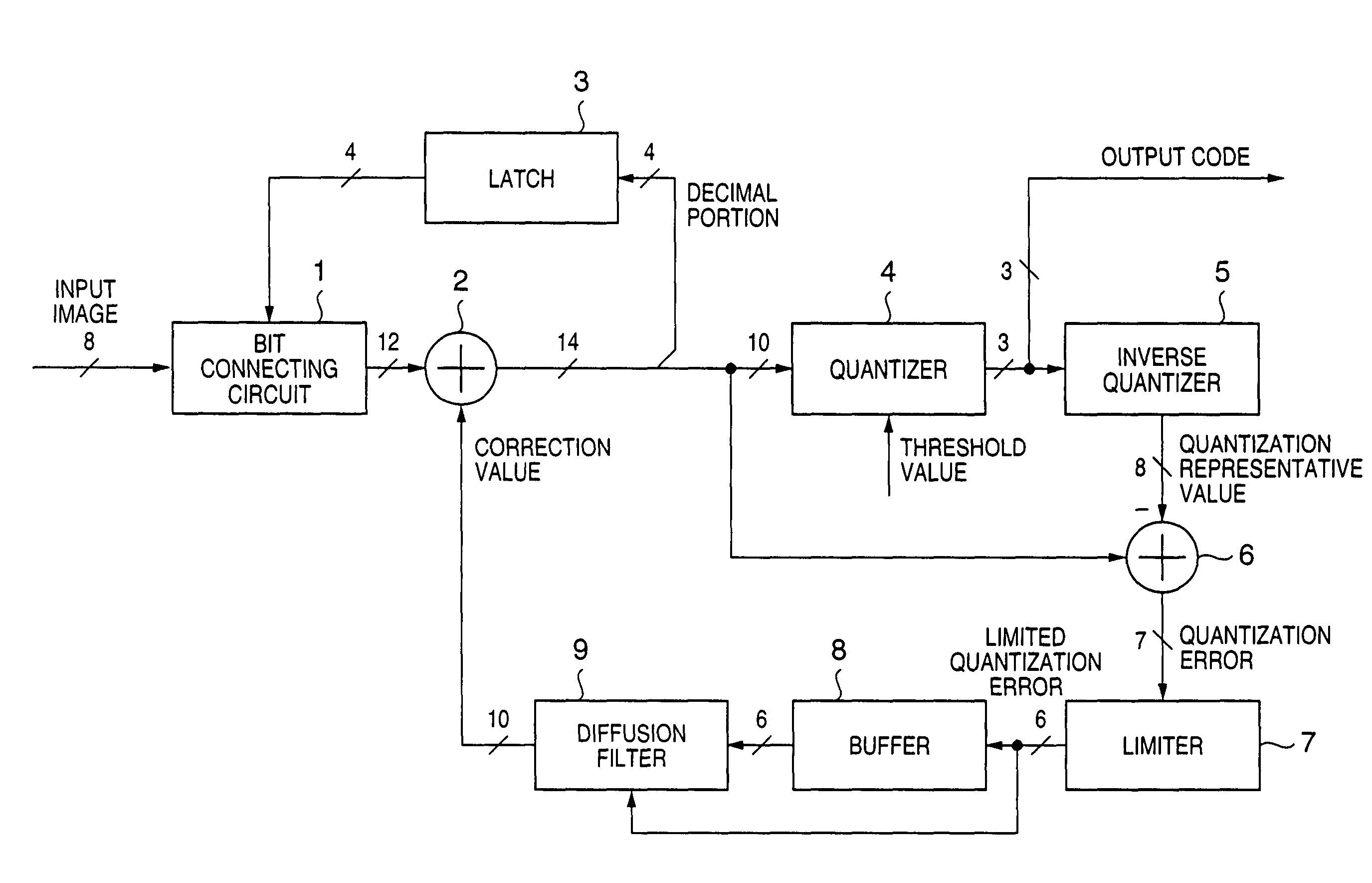
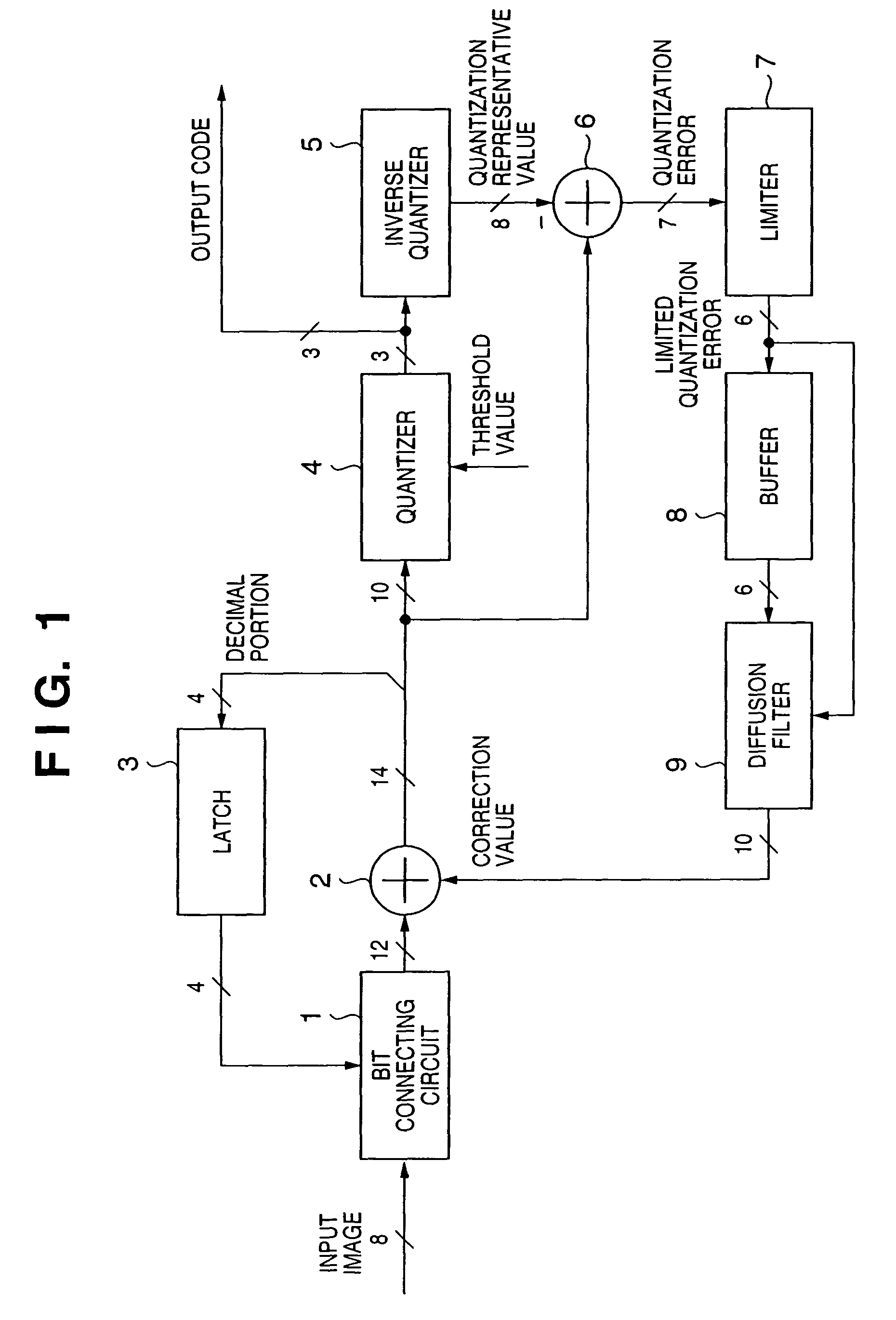
[0049]An embodiment of the present invention is described below in detail with reference to the accompanying drawings. FIG. 1 is a block diagram for explaining the arrangement of an image processing apparatus according to a first embodiment of the present invention.

[0050]Referring to FIG. 1, a bit connecting circuit 1 connects the cumulative value of decimals from a latch 3 to the lower bits of input image data. An adder 2 adds a correction value from a diffusion filter 9 to the input image data. The latch 3 delays the decimal portion of the adder 2 by one pixel. A quantizer 4 compares the integral portion of the adder 2 with a threshold value and converts the integral portion into an output code. An inverse quantizer 5 generates a quantization representative value from the output code. A subtracter 6 subtracts the quantization representative value from the value immediately before quantization to generate a quantization error. A limiter 7 limits the quantization error from the subt...

second embodiment

[0061]FIG. 3 is a block diagram showing the arrangement of an image processing apparatus according to the second embodiment of the present invention. Referring to FIG. 3, reference numerals 11 and 12 denote adders; 13, a latch; 14, a quantizer; 15, an inverse quantizer; 16, a subtracter; 17, a limiter; 18, a line buffer; and 19, a diffusion filter. Only parts different from the first embodiment is described below.

[0062]In this embodiment, the number of bits of the latch 13 is extended by m bits, and not only the decimal portion but also m lower bits of the integral portion after error correction are cumulatively added, thereby decreasing the capacity of the line buffer 18.

[0063]Hence, as in the first embodiment, the decimal portion of the output from the latch 13 is connected to the lower bits of input image data. On the other hand, the m-bit integral portion is added to the input image by the adder 11. For this reason, the output after bit connection has 13 bits. The separated inte...

third embodiment

[0072]FIG. 4 is a block diagram for explaining the arrangement of an image processing apparatus according to the third embodiment of the present invention. Referring to FIG. 4, reference numeral 20 denotes a white / black pixel detector; 21, a latch; 22, a code replacement circuit; and 23, a quantization error replacement circuit. Only parts different from the second embodiment is described below.

[0073]The white / black pixel detector 20 detects white pixels (0 in the second embodiment) and black pixels (255 in the second embodiment) of input image data. The detection result is output to the latch 21 and replacement circuits 22 and 23.

[0074]When the white / black pixel detector 20 detects a white or black pixel, the latch 21 clears the latch to prevent error propagation to the next and subsequent pixels. Accordingly, any inappropriate result such as smear at a highlight portion or omission of a thin line due to unnecessary error propagation can be suppressed.

[0075]When a white pixel is de...


PUM


Abstract

This disclosure relates to decreasing the required buffer memory capacity while reducing the impact of an arithmetic error in error diffusion processing. A quantization circuit (4) quantizes input image data and outputs an output code. The quantization error generated in the quantization circuit (4) is calculated by an inverse quantization circuit (5) and subtracter (6). The calculated quantization error is stored in a buffer (8). Since the buffer (8) only needs to have a size capable of storing the quantization error, the size can be made smaller than before. A diffusion filter (9) diffuses the quantization error using a quantization error or the like, which is stored in the buffer (8). A latch (3) and bit connector (1) can usefully reduce the impact of an arithmetic error in error diffusion processing on the next input image data.

Description

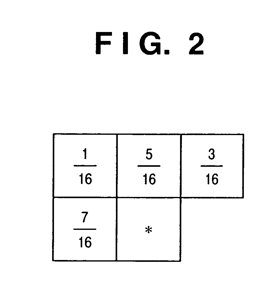
FIELD OF THE INVENTION[0001]The present invention relates to a method and apparatus for image processing and, more particularly, to an image processing method and apparatus for quantizing input data into binary or multilevel data while storing the difference between an input image density and an output image density by an error diffusion method.BACKGROUND OF THE INVENTION[0002]To express input multilevel data as binary data or as multilevel data of fewer levels than that of the input binary data, pseudo halftone processing is conventionally used. As an example of the pseudo halftone processing, an error diffusion method is known. This error diffusion method is published in “An Adaptive Algorithm for Spatial Gray Scale” in Society for Information Display 1975 Symposium Digest of Technical Papers, 1975, 36. In this method, let P be the pixel of interest, v be the density of the pixel, v0, v1, v2, and v3 be the densities of pixels P0, P1, P2, and P3 which are present in the neighborhoo...

Claims


Application Information

Patent Timeline
Patent Type & Authority Patents(United States)
IPC IPC(8): G06F3/00G06K15/00H04N1/405
CPCH04N1/4052H04N1/4057
Inventor ISHIKAWA, HISASHI
Owner CANON KK
Learn More