Data forwarding engine
- Summary
- Abstract
- Description
- Claims
- Application Information
AI Technical Summary
Benefits of technology
Problems solved by technology
Method used
Image

Examples
first embodiment
[0036]By eliminating the centralized management system, the costly maintenance of maintaining, for example, which one of the processors issued a memory access request can be reduced or eliminated entirely. FIG. 4 shows a distributed multi-processor out-of-order system according to the present invention. In this embodiment, a processor 103 issues a memory access request (e.g., a read request) 118 and a memory access request 127. A processor 106 issues a memory access request 124, and a processor 115 issues a memory access request 121. Each processor can be a pipelined processor and have multiple memory access requests outstanding. Each of the memory access requests 118, 121, 124, and 127 includes a tag. The tag includes a priority, processor identification number (“proc ID”), and a processor access sequence number (“P-SeqNo”). The processor ID identifies the processor that issued the memory access request so that the data fetched due to the memory access request is sent to the proces...
second embodiment
[0048]FIG. 6 shows a distributed multi-processor out-of-order system according to the present invention. In this embodiment, the storage unit 171 includes two different memory types, e.g., a memory type one that is a relatively slow memory such as dynamic random access memory (“DRAM”) and a memory type two that is a relatively fast memory such as static random access memory (“SRAM”). As FIG. 6 shows, the address A1 is located in the slower memory type 1 and thus the memory access latency to access the data at address A1 is greater than the memory access latency to access the data at addresses A0, A2, and A3. The controller 148 knows when the data corresponding to the different requests arrives from the storage unit (e.g., given the address, the controller 148 knows the latency to fetch the data from that address) and retags the data with, for example, the processor ID, the processor access sequence number, and the data sequence number so that the data unit can properly return to the...
third embodiment
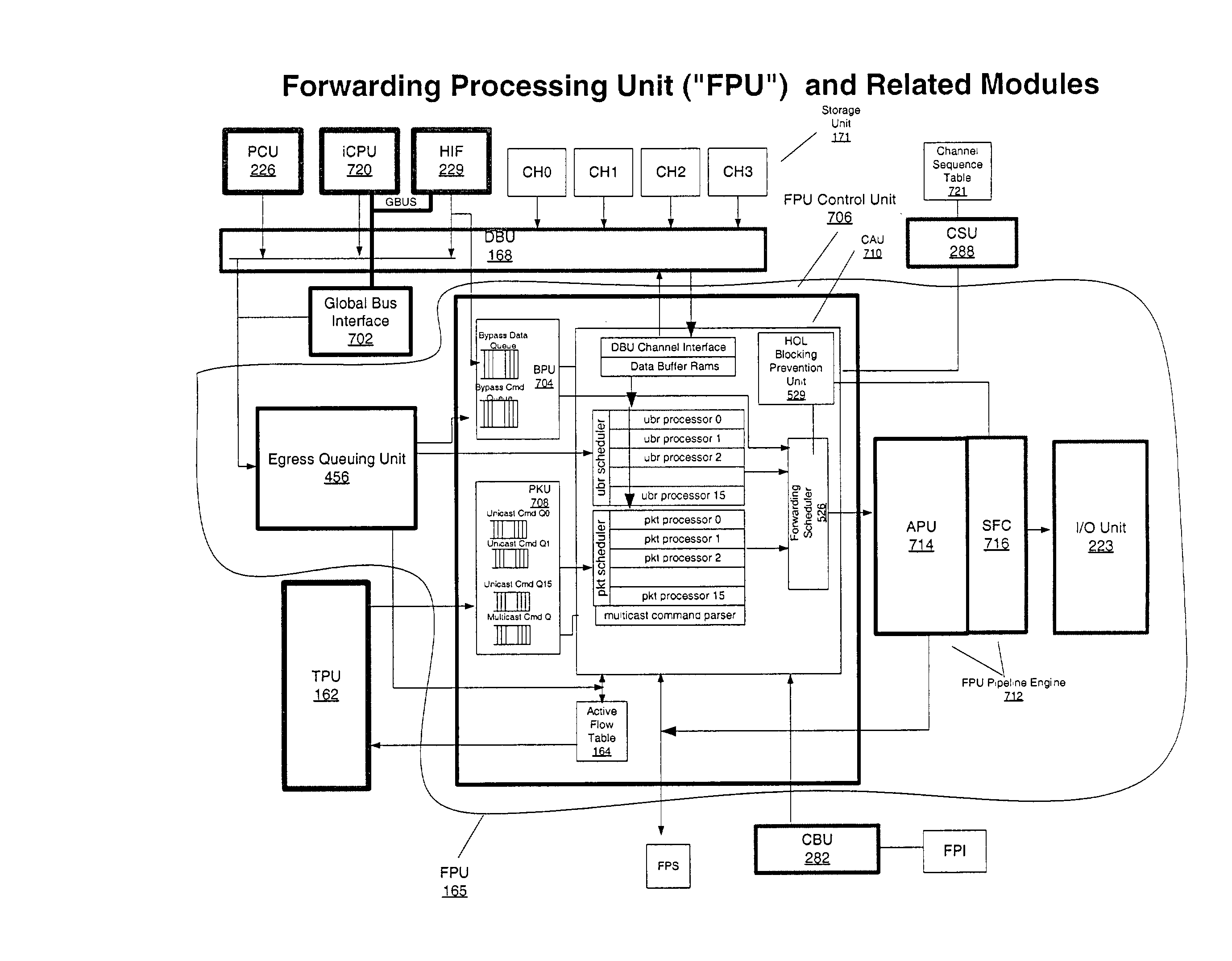
[0049]FIG. 7 shows a distributed multi-processor out-of-order system according to the present invention. In this embodiment, the storage unit 171 includes a channel 0, a channel 1, a channel 2, and a channel 3. By using multiple memory channels, memory access parallelism is increased (e.g., with multiple channels, more simultaneous accesses to memory can occur than if only one channel was used) which increases the bandwidth. Each of the memory channels has a corresponding channel controller, e.g., channel 0 has a channel 0 controller, channel 1 has a channel 1 controller, channel 2 has a channel 2 controller, and channel 3 has a channel 3 controller. Each of the channel controllers adds a tag to the data retrieved from the corresponding memory channel to produce a data unit. The tag added to the data corresponds to the tag of the memory access request that specified the address from which the data was retrieved. The tag added to the data includes the processor ID and the data sequen...
PUM
 Abstract
Description
Claims
Application Information
 - R&D
- Intellectual Property
- Life Sciences
- Materials
- Tech Scout
- Unparalleled Data Quality
- Higher Quality Content
- 60% Fewer Hallucinations
Browse by: Latest US Patents, China's latest patents, Technical Efficacy Thesaurus, Application Domain, Technology Topic, Popular Technical Reports.
© 2025 PatSnap. All rights reserved.Legal|Privacy policy|Modern Slavery Act Transparency Statement|Sitemap|About US| Contact US: help@patsnap.com