Magnetostrictive torque sensor and method of manufacturing same

a technology of magnetostrictive torque and manufacturing method, which is applied in the direction of electrical measurements, instruments, measurement devices, etc., can solve the problems of inability to increase the manufacturing efficiency the manufacturing of magnetostrictive torque sensors, etc., and achieves the effect of minimizing the source of variation in output characteristics, simple structure and small siz

Active Publication Date: 2011-09-06
HONDA MOTOR CO LTD
View PDF33 Cites 8 Cited by
  • Summary
  • Abstract
  • Description
  • Claims
  • Application Information

AI Technical Summary

Benefits of technology

[0033]An object of the present invention is to provide a magnetostrictive torque sensor, which is simple in structure and small in size while effectively minimizing sources of variations in output characteristics, and which will not lead to variations in output characteristics even though the axial length of a magnetostrictive film is reduced. Another object of the present invention is to provide a method of manufacturing such a magnetostrictive torque sensor.

Problems solved by technology

Furthermore, since a complex masking process is required to fabricate the first magnetostrictive film 244a and the second magnetostrictive film 244b on the steering shaft 210, the process of manufacturing the magnetostrictive torque sensor 208 also is complex, and manufacturing efficiency of the magnetostrictive torque sensor 208 cannot be increased, thereby posing limitations on efforts to lower the cost of the magnetostrictive torque sensor 208.

Method used


Image

  • Magnetostrictive torque sensor and method of manufacturing same
  • Magnetostrictive torque sensor and method of manufacturing same
  • Magnetostrictive torque sensor and method of manufacturing same

Examples


Embodiment Construction

[0071]A magnetostrictive torque sensor according to an embodiment of the present invention, together with a method of manufacturing such a magnetostrictive torque sensor, will be described below with reference to FIGS. 1 through 10.

[0072]First, an electric power steering apparatus 10 incorporating a magnetostrictive torque sensor therein according to an embodiment of the present invention will be described below with reference to FIG. 1.

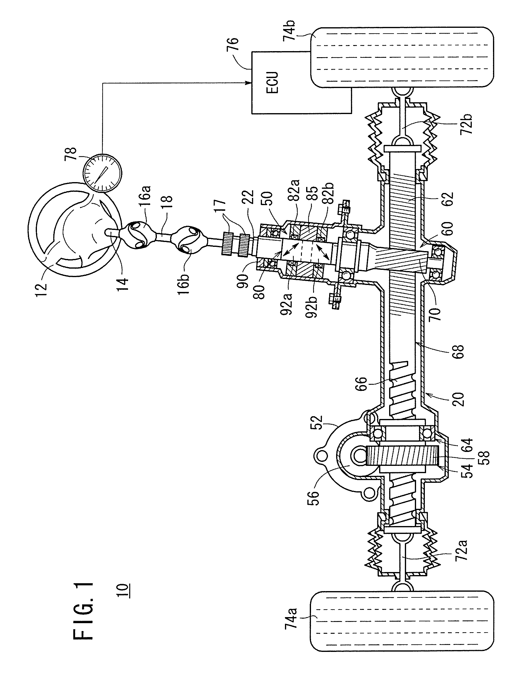
[0073]As shown in FIG. 1, the electric power steering apparatus 10 is arranged such that a steering torque and a steering angle, which are produced when the driver of a vehicle incorporating the electric power steering apparatus therein 10 turns a steering wheel 12, are applied to a steering shaft 22 of a steering gearbox 20 through a steering shaft 14, a first universal joint 16a, an intermediate shaft 18, a second universal joint 16b, and couplings 17 (e.g., serrations).

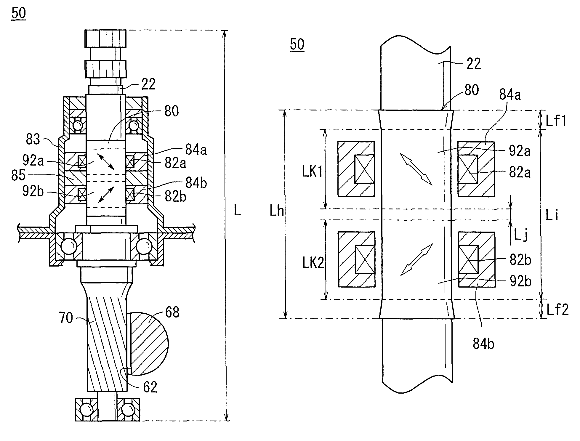
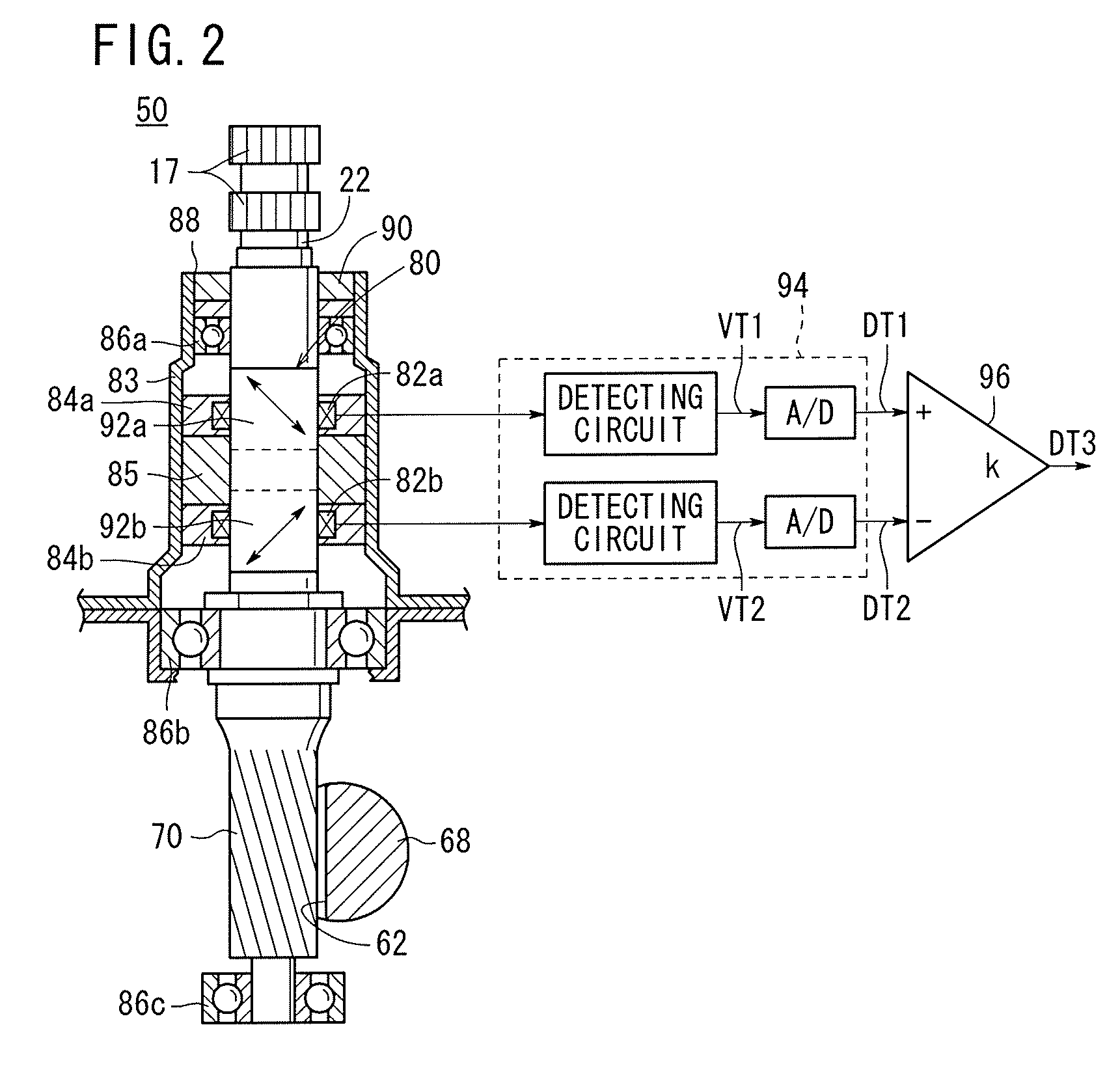
[0074]The steering gearbox 20 comprises the steering shaft 22 (shaft member), a...


PUM

PropertyMeasurementUnit
thicknessaaaaaaaaaa
thicknessaaaaaaaaaa
axial lengthaaaaaaaaaa

Abstract

A magnetostrictive torque sensor includes a single magnetostrictive film disposed on a steering shaft, and first and second coils for detecting changes in a magnetic property of the magnetostrictive film. The single magnetostrictive film includes a first anisotropic region and a second anisotropic region, having respective magnetic anisotropies inverse to each other. The first coil is disposed in confronting relation to the first anisotropic region, whereas the second coil is disposed in confronting relation to the second anisotropic region.

Description

CROSS-REFERENCE TO RELATED APPLICATION[0001]This application is based upon and claims the benefit of priority from Japanese Patent Application No. 2009-101041 filed on Apr. 17, 2009, of which the contents are incorporated herein by reference.BACKGROUND OF THE INVENTION[0002]1. Field of the Invention[0003]The present invention relates to a magnetostrictive torque sensor for detecting torque based on a change in a magnetic property due to magnetostriction, as well as to a method of manufacturing such a magnetostrictive torque sensor.[0004]2. Description of the Related Art[0005]Generally, an electric power steering apparatus on a vehicle includes a motor incorporated in a steering system, and a controller for controlling the power supplied from the motor in order to reduce a steering torque that is applied to the steering shaft by the driver of the vehicle.[0006]As shown in FIG. 11 of the accompanying drawings, an electric power steering apparatus 200 of the related art includes a stee...

Claims


Application Information

Patent Timeline
Patent Type & Authority Patents(United States)
IPC IPC(8): G01R3/00G01L3/00
CPCG01L3/102H01F10/14H01F41/24G01L3/103H01L41/125Y10T29/49007Y10T29/4902H10N35/101
Inventor YONEDA, ATSUHIKOSHIMIZU, YASUO
Owner HONDA MOTOR CO LTD
Why Eureka
Try Eureka