
High-resolution synthetic aperture radar device and antenna for one such radar

a synthetic aperture radar and high-resolution technology, applied in the direction of measurement devices, instruments, radio wave reradiation/reflection, etc., can solve the problems of heavy and thus expensive payloads, and achieve the effect of small antenna area

Active Publication Date: 2011-09-06
AIRBUS DEFENCE & SPACE
View PDF20 Cites 10 Cited by
  • Summary
  • Abstract
  • Description
  • Claims
  • Application Information

AI Technical Summary

Benefits of technology

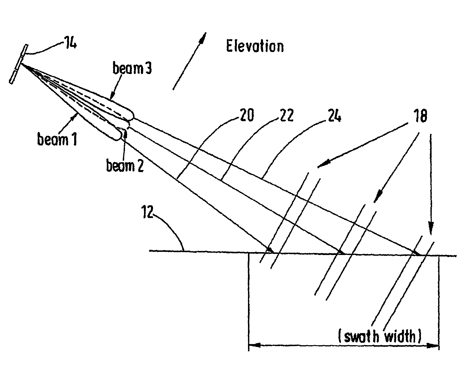
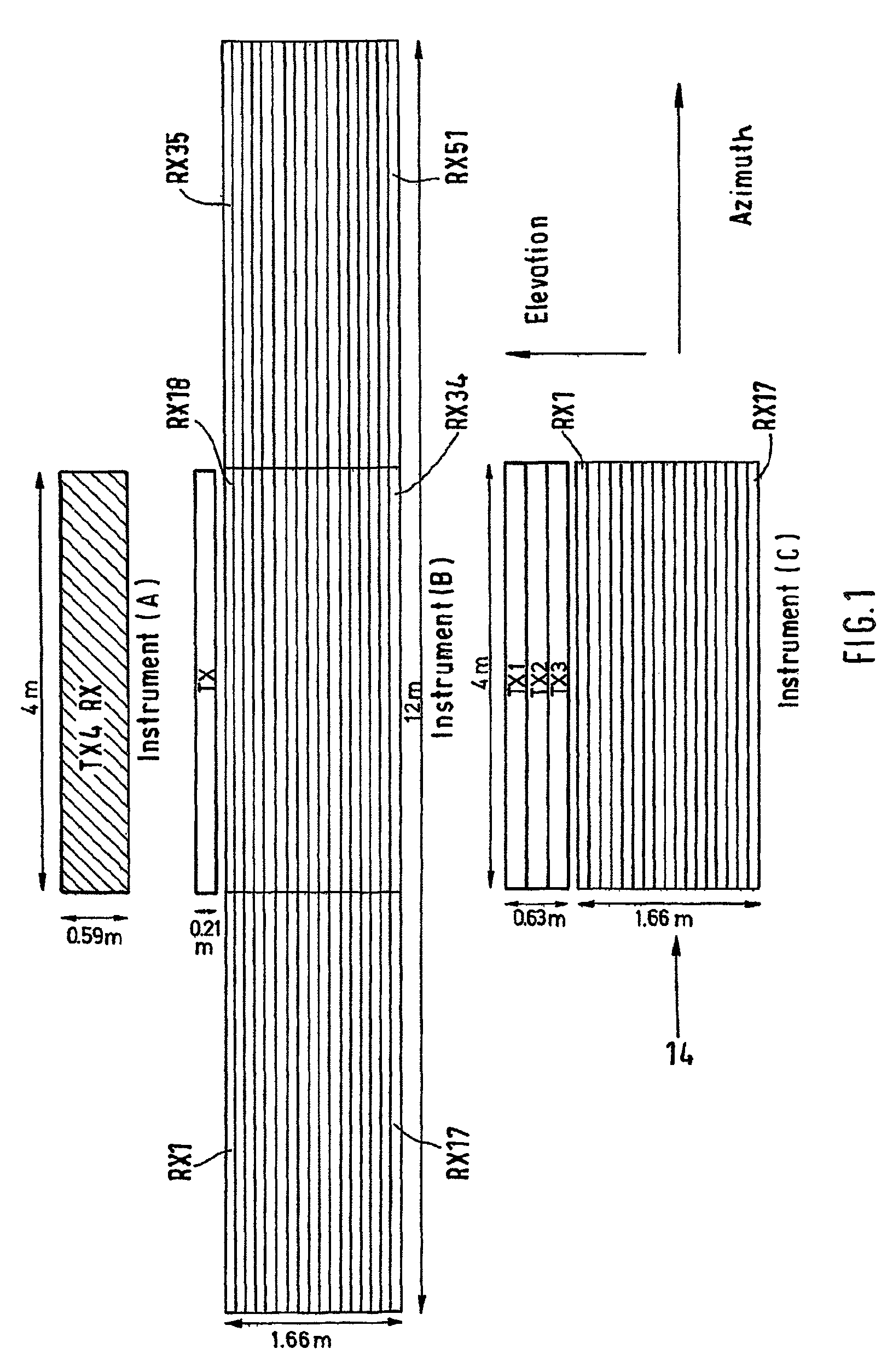
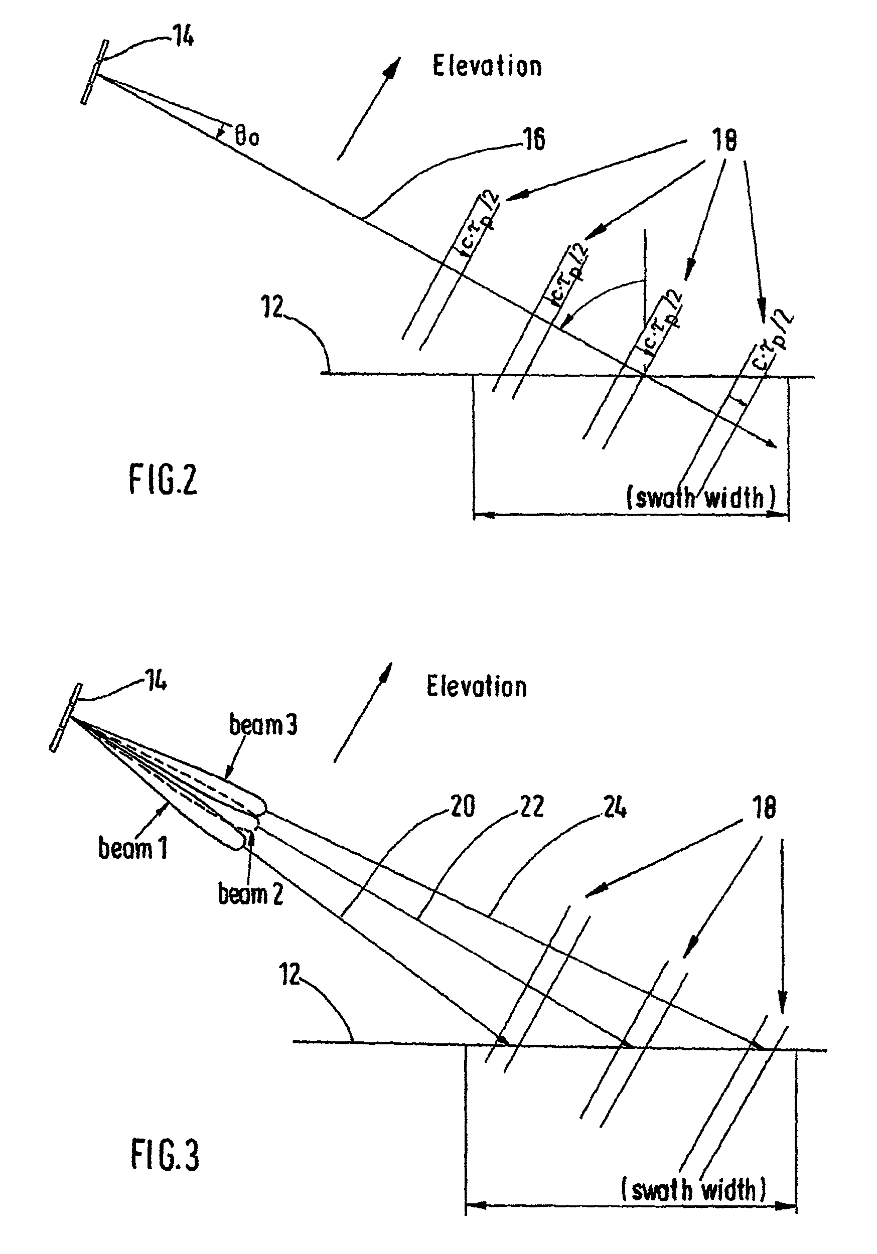
The present invention provides a high-resolution synthetic aperture radar device and an antenna for it that can scan the broadest swaths with high azimuth resolution using a smaller antenna area than conventional SAR. The device uses a transmitting antenna and a receiving antenna with sub-apertures arranged in elevation to achieve this. The pulse signals are emitted at irregular time intervals, and data gaps are avoided by emitting fewer pulses and using a resampling method to reconstruct the missing scanning values. The device can be built to be smaller and lighter than conventional SAR, reducing costs. The sub-apertures form fewer azimuth apertures, and a resampling method is used for processing the received radar echoes. The device can also use multiple transmitting antennas simultaneously in the frequency multiplex to achieve a high signal-to-noise ratio. The receiving channel is provided for each radar echo to avoid range ambiguities in the SAR image. The device can also carry out a space-based separation of the reflected radar echoes.

Problems solved by technology

However, one disadvantage of the HRWS SAR lies in the large antennas, which in particular with satellite-based SAR lead to heavy and thus expensive payloads.

Method used


Image

  • High-resolution synthetic aperture radar device and antenna for one such radar
  • High-resolution synthetic aperture radar device and antenna for one such radar
  • High-resolution synthetic aperture radar device and antenna for one such radar

Examples


Embodiment Construction

[0008]According to embodiments of the present invention, a high-resolution synthetic aperture radar device and an antenna for a high-resolution synthetic aperture device is provided, which make it possible to scan the broadest possible swaths with high azimuth resolution with a much smaller antenna area than with an HRWS SAR.

[0009]In embodiments, a high-resolution synthetic aperture radar device includes at least one transmitting antenna for producing radar beams for scanning an object, and a receiving antenna for receiving radar beams reflected by the object. The receiving antenna has several sub-apertures arranged in elevation, and the high-resolution synthetic aperture radar device is embodied such that pulse signals are emitted at irregular time intervals. In further embodiments, an antenna for a high-resolution synthetic aperture device includes two or more transmitting antennas, which are embodied for emitting respectively one radar beam in the microwave range, and a receiving...


PUM


Abstract

The invention relates to a high-resolution synthetic aperture radar device (10) comprising at least one transmitting antenna (TX1-TX3) for producing and emitting radar pulses for scanning an object (12), a receiving antenna (14) for receiving the radar beams (20, 22, 24) emitted and reflected by an object, wherein the receiving antenna (14) has several sub-apertures (RX1-RX17) arranged along elevation, which form a minimum of azimuth apertures, wherein the high-resolution synthetic aperture radar device is embodied such that pulse signals (18) are emitted at irregular time intervals.

Description

CROSS-REFERENCE TO RELATED APPLICATIONS[0001]The instant application is a U.S. National Stage of International Application No. PCT / DE2006 / 002279 filed Dec. 20, 2006, and claims priority of German Patent Application No. 10 2005 062 031.0 filed Dec. 22, 2005. The disclosure of International Application No. PCT / DE2006 / 002279 is expressly incorporated by reference herein in its entirety.BACKGROUND OF THE INVENTION[0002]1. Field of the Invention[0003]The invention relates to a high-resolution synthetic aperture radar device and an antenna for a high-resolution synthetic aperture radar device.[0004]2. Discussion of Background Information[0005]In synthetic aperture radar (SAR), an object, such as, for example, the earth's surface, is scanned by a short moving antenna, via which pulse signals, i.e., pulses are emitted at a defined time interval and the echo signals, i.e., the pulse signals reflected by scanned objects, are received. The direction of movement of the short antenna is also ref...

Claims


Application Information

Patent Timeline
Patent Type & Authority Patents(United States)
IPC IPC(8): H04K3/00
CPCG01S13/9035G01S2013/9058G01S13/9058G01S13/904G01S13/22
Inventor GRAFMUELLER, BERNHARDSCHAEFER, CHRISTOPH
Owner AIRBUS DEFENCE & SPACE
Learn More