Axle spindle nut assembly for heavy-duty vehicles

a technology for axle spindle nuts and heavy-duty vehicles, which is applied in the direction of screws, threaded fasteners, bolts, etc., can solve the problems of excessive axial end play of the wheel end assembly, detrimental to its performance, and maintenance of the proper clamp load, so as to prevent substantial rotation of the nut

Active Publication Date: 2011-09-13
HENDRICKSON USA L L C
View PDF7 Cites 46 Cited by
  • Summary
  • Abstract
  • Description
  • Claims
  • Application Information

AI Technical Summary

Benefits of technology

[0016]One objective of the present invention is to provide an axle spindle nut assembly that is economical, durable, and less complex to install and remove than axle spindle nut assemblies of the prior art.
[0017]Another objective of the present invention is to provide an axle spindle nut assembly that minimizes or eliminates the possibility of an installer over or under-torquing the nut assembly.
[0018]Yet another objective of the present invention is to provide an axle spindle nut assembly that can reduce the amount of torque required to preload the bearing cones.
[0019]Still another objective of the present invention is to provide an axle spindle nut assembly that indicates when the proper position of the nut has been attained.
[0021]These objectives and others are also obtained by the axle spindle nut assembly for securing a wheel end assembly of a heavy-duty vehicle on an axle spindle of an axle of the present invention. The axle spindle has an outboard end formed with a keyway and threads, and the wheel end assembly includes an outboard bearing and an inboard bearing removably mounted on the axle spindle for rotatably mounting a wheel hub on the axle spindle. The axle spindle nut assembly includes a first washer formed with an inboard surface and an outboard surface. The first washer is disposed on the axle spindle with the inboard surface adjacent to the outboard bearing. A nut is formed with threads for threadably engaging the axle spindle threads, and the nut is capable of being tightened to a selected torque level against the outboard surface of the first washer. The nut has an outboard surface formed with a plurality of features. The nut features include a recess with radially inwardly extending teeth, and the recess communicates with a pair of spaced-apart slots. The recess is formed with relief areas free of the teeth adjacent to each one of the pair of slots. A second washer is disposed outboard of the nut on the axle spindle. The second washer is formed with a tab for engaging the keyway of the axle spindle to prevent rotation of the second washer about the axle spindle. The second washer also is formed with a plurality of mating features for mechanically engaging the radially inwardly extending teeth of the nut. The washer mating features include radially outwardly extending teeth formed on an outer periphery of the washer whereby substantial rotation of the nut is prevented. A selected one of the washer and the nut is formed with at least one generally circumferentially-extending nub. A pair of fasteners secure the second washer to the nut by insertion of the fasteners into respective ones of the slots. The nub aids contact by the fasteners with the second washer and the nut so that the second washer thereby is secured to the nut and is removable by removal of the fasteners and application of inboard pressure against the second washer at a selected one of the slot relief areas of the nut.

Problems solved by technology

Therefore, the wheel end assembly also must be sealed to prevent leakage of the lubricant, and also to prevent contaminants from entering the assembly, both of which could be detrimental to its performance.
Such an assembly, while performing adequately in certain applications, can exhibit disadvantages associated with installation and maintenance of the proper clamp load.
For example, if the clamp force on the bearing cone and spacer group is too low, there may be excessive end play of the bearings, which in turn creates excessive axial end play of the wheel end assembly relative to the axle spindle.
Such excessive end play may allow undesirable movement of the main seal, which in turn potentially reduces the life of the main seal and the bearings.
If the clamp force on the bearing cone and spacer group is too high, the bearings may effectively be over-compressed, interfering with their rotation and causing them to possibly wear out prematurely.
Axle spindle nut assemblies of the prior art include distinct disadvantages associated with proper installation of the nut assembly to provide the desired clamp force on the bearing cone and spacer group.
However, in these applications, proper installation of the axle spindle nut assembly on the wheel end assembly includes a complex procedure in which an inner nut of the axle spindle nut assembly is installed and torqued to a predetermined force level, and then a lock washer and an outer nut are installed and the outer nut is torqued to another predetermined level.
Because of manufacturing variances in thread form and the associated variation in thread lash between each of the nuts and the threads on the outboard end of the axle spindle, the procedure can often become quite complex.
Such a complex procedure undesirably increases the time and skill level involved to assemble the wheel end assembly, both during initial manufacturing and during maintenance-related servicing, which in turn increases the possibility of human error.
However, the use of a bearing spacer to simplify the procedure for installation of the axle spindle nut assembly undesirably increases the weight and cost of the wheel end assembly.
In addition, to achieve an acceptable level of axial end play of the wheel end assembly relative to the axle spindle, the axle spindle nut assembly must undesirably be torqued to a high level when a bearing spacer is employed.
More particularly, some wheel end assemblies include specialized, tight-tolerance unitized inboard and outboard bearings, which may reduce the need for a complex installation procedure for the axle spindle nut assembly, but still may require undesirably high torque on the axle spindle nut assembly to achieve an acceptable level of axial compression of the unitized bearing cone clamp group to obtain the desired bearing adjustment of the wheel end assembly.
The use of unitized bearings also significantly increases the cost associated with the wheel end assembly and is therefore undesirable.
Furthermore, the use of the multiple-nut axle spindle nut assemblies of the prior art to secure any type of wheel end assembly increases the possibility of human error, such as, for example, one or more of the nuts in the axle spindle nut assembly being inadvertently torqued to an undesirable level, thereby undesirably over or under compressing the bearing cone and spacer group.
However, since the outer nut is torqued after the inner nut has been torqued, over-torquing of the outer nut may cause the inner nut to loosen even if the inner nut has been properly torqued.
More particularly, over-torquing of the outer nut may create excessive inboardly-directed pressure on the outboard face of the inner nut, which in turn causes the outboard thread faces of the inner nut to move inboardly, and thus away from the mating inboard thread faces on the axle spindle.
Since engagement of these mating thread faces is necessary for the inner nut to securely maintain its position on the axle spindle, such separation of the thread faces can cause the inner nut to loosen, thereby under-compressing the bearing cone and spacer group.
Prior art axle spindle nut assemblies also lack means to indicate when the proper clamp load has been achieved, which is a disadvantage in some applications, such as when a relatively high level of torque on the spindle nut assembly is required.
Then, the technician typically will continue to tighten the spindle nut assembly, estimating the amount of torque being imposed on the axle spindle nut assembly, and may thus torque the nut assembly to an improper level.
A torque multiplier is a device known to those skilled in the art, and generally is accepted as being an unreliable method of developing the correct amount of torque on the nut, thereby potentially causing the technician to torque the axle spindle nut to an improper level.
As described above, if the torque level is too low, the bearing cone and spacer group may undesirably be under compressed, and if the torque level is too high, the bearing cone and spacer group may undesirably be over compressed.
These disadvantages of prior art axle spindle nut assemblies make it desirable to develop an economical axle spindle nut assembly that is easy to install and remove, minimizes or eliminates the possibility of an installer over or under-torquing the nut assembly, indicates when the proper position of the nut of the spindle nut assembly has been attained, and can reduce the amount of torque required to preload the bearing cones.

Method used


Image

  • Axle spindle nut assembly for heavy-duty vehicles
  • Axle spindle nut assembly for heavy-duty vehicles
  • Axle spindle nut assembly for heavy-duty vehicles

Examples


first embodiment

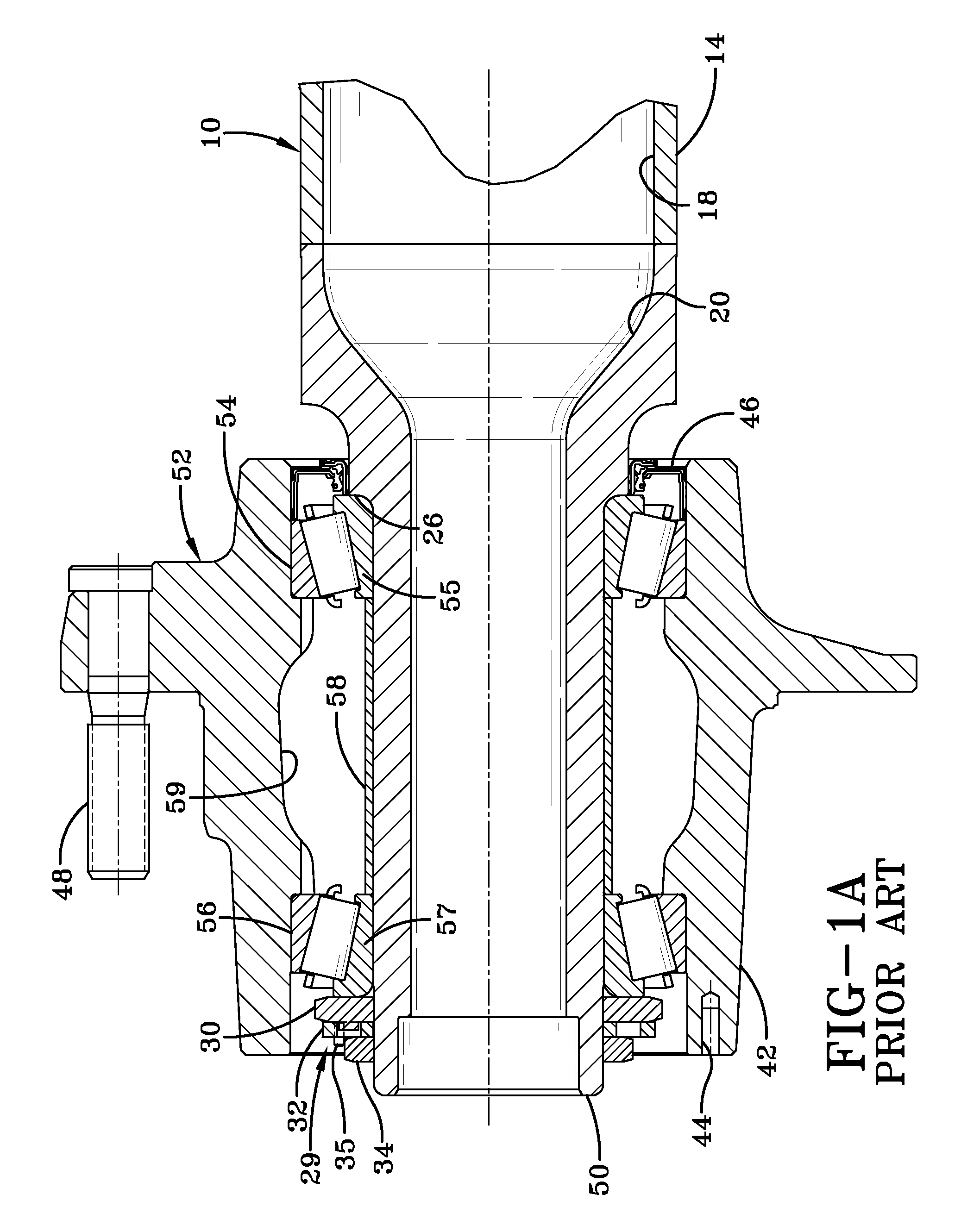
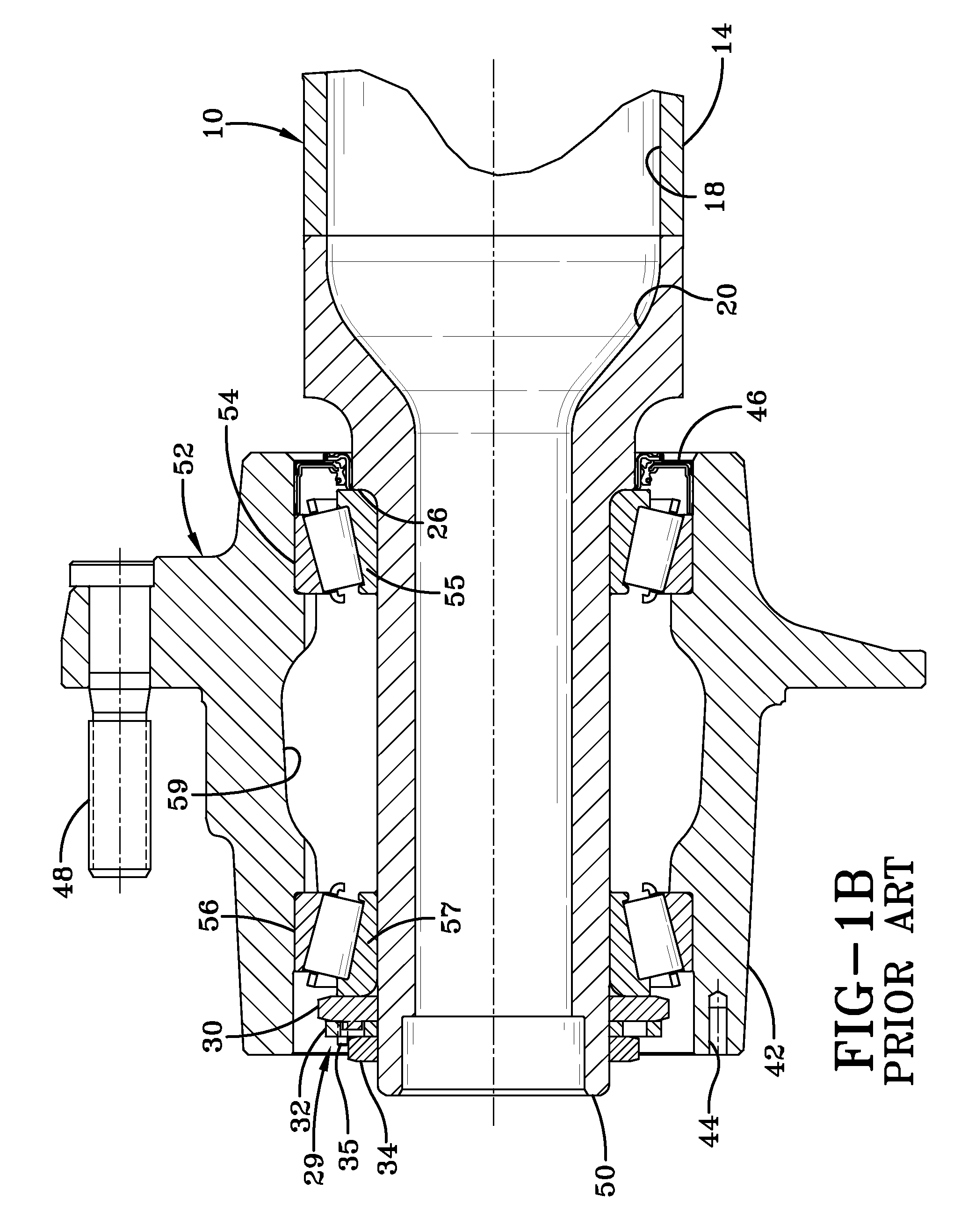
[0064]Turning now to FIG. 7, a first embodiment axle spindle nut assembly of the present invention is indicated generally at 200 and is shown incorporated into first axle spindle 50 and wheel end assembly 52, with the exception that bearing spacer 58 (FIG. 1) preferably is not included, as will be described in greater detail below. Axle spindle nut assembly 200 includes an optional inner washer 202, an axle spindle nut 212, an outer washer 230, and at least one screw 244. Axle spindle nut 212, washers 202, 230 and screw 244 cooperate to secure bearings 54, 56 of wheel end assembly 52 in place, and to preload bearing cones 55, 57.

[0065]More particularly, with additional reference to FIGS. 8 and 9, optional inner washer 202 is a flat washer having an inboard face 204 that is proximate to and contacts outboard bearing cone 57 of wheel end assembly 52 in an assembled state. Inner washer 202 also includes an outboard face 206, which is proximate to and contacts nut 212 in an assembled st...

sixth embodiment

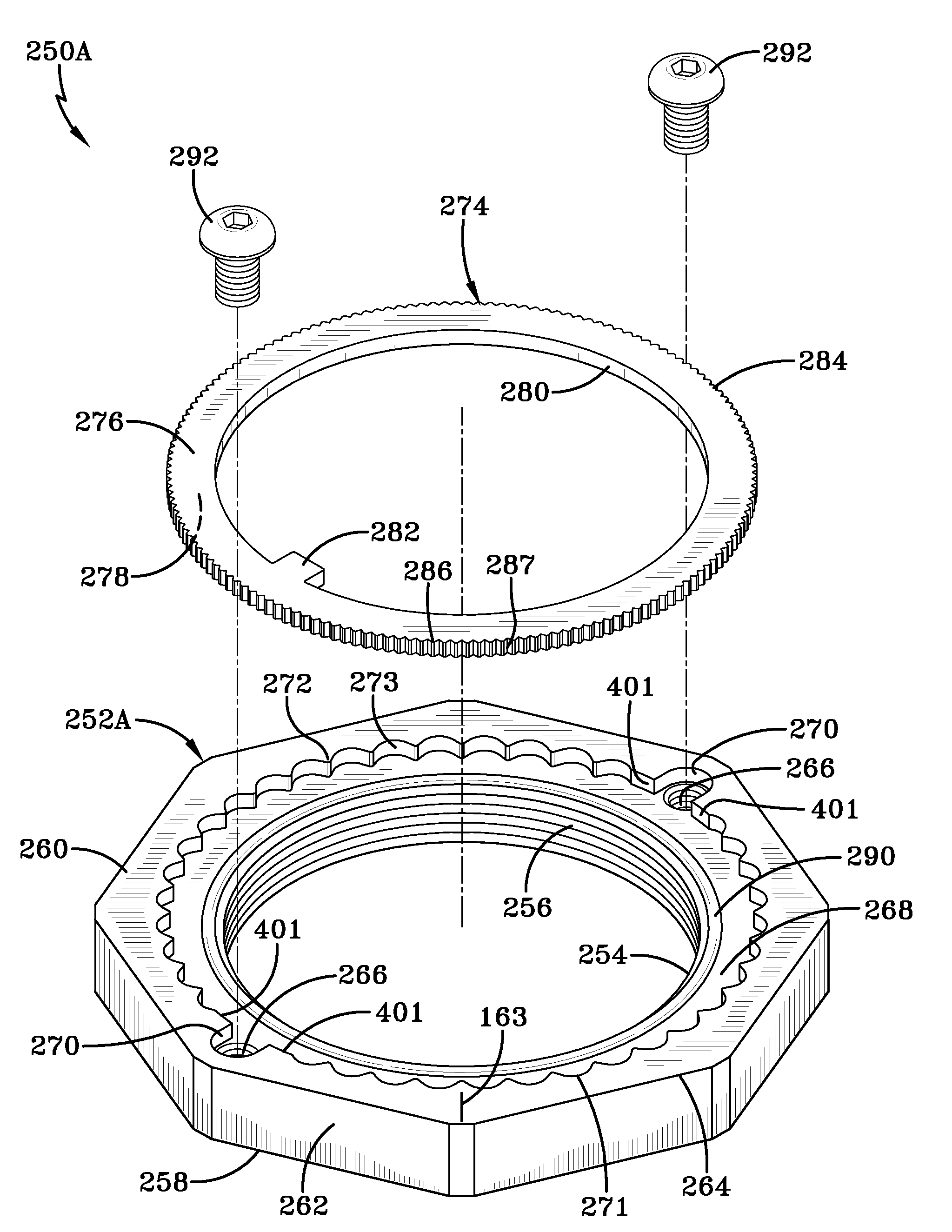
[0096]It is understood that optional washer 202 having graduations 154, can be used with third, fourth, fifth, and sixth embodiment axle spindle nut assemblies 250A-D, and nuts 252A-D each having an indicator mark 163, respectively, without affecting the overall concept of the present invention. It is further understood that circumferentially-extending nubs 290, 290′, circumferentially-extending arcuate-shaped nubs 290″, and circumferentially-extending nub or ramp 290′″, each could be disposed on outer washer 274 of axle spindle nut assemblies 250A-D, respectively, without affecting the overall concept of the invention.

[0097]Turning now to FIGS. 19-22, a seventh embodiment axle spindle nut assembly of the present invention is shown and is indicated generally at 300. Third embodiment axle spindle nut assembly 300 is similar in structure and operation to first embodiment axle spindle nut assembly 200 and second embodiment axle spindle nut assembly 250, with the exception that mating f...

second embodiment

[0100]With reference now to FIG. 22, outer washer 310 is formed with a tab 311, which engages axle spindle keyway 196 (FIG. 7) as described above for first and second embodiment outer washers 230, 274. Outer washer 310 includes a first face 312 and a second face 314. At least one of first face 312 and second face 314 is formed with a recess 316 proximate an inner circumference 317 of washer 310. An outer edge 319 of recess 316 is formed with radially inwardly extending features 318, such as teeth. Radially outwardly extending grooves 326 are formed between teeth 318. Radially outwardly extending teeth 308 formed on nut 302 extend into selected ones of grooves 326 in outer washer 310, while radially inwardly-extending teeth 318 formed on the outer washer extend into grooves 324 in the nut. In this manner, radially outwardly extending teeth 308 formed on nut 302 positively mechanically engage and interlock with mating radially inwardly extending teeth 318 formed on outer washer 310, o...


PUM


Abstract

An axle spindle nut assembly secures a wheel end assembly on an axle spindle. The wheel end assembly includes outboard and inboard outboard bearings that are immovably mounted on the axle spindle, and a wheel hub which is rotatably mounting on the bearings. The spindle nut assembly includes a nut that threads onto an outboard end of the axle spindle, and is tightened against the outboard bearing to a selected torque level. The nut includes an outboard surface that is formed with a plurality of features. A washer is formed with a tab that engages a keyway of the axle spindle outboardly of the nut, and with a plurality of mating features that mechanically engage the features formed in the outboard surface of the nut to prevent substantial rotation of the nut after the nut has been tightened to the selected torque level.

Description

CROSS-REFERENCE TO RELATED APPLICATIONS[0001]This application is a continuation-in-part of U.S. Non-Provisional Patent Application Ser. No. 11 / 494,438, filed Jul. 27, 2006, which claims the benefit of U.S. Provisional Patent Application Ser. No. 60 / 713,889, filed on Sep. 2, 2005, and U.S. Provisional Patent Application Ser. No. 60 / 772,077, filed on Feb. 10, 2006.BACKGROUND OF THE INVENTION[0002]1. Technical Field[0003]The invention relates to wheel end assemblies and in particular to wheel end assemblies for heavy-duty vehicles, such as tractor-trailers. More particularly, the invention is directed to an axle spindle nut assembly of a wheel end assembly for a heavy-duty vehicle, which includes a nut and a washer each formed with a sufficient number of interlocking features that secure components of the wheel end assembly on an axle spindle, such that during assembly, the possibility of over or under tightening the nut is minimized or eliminated.[0004]2. Background Art[0005]For many ...

Claims


Application Information

Patent Timeline
Patent Type & Authority Patents(United States)
IPC IPC(8): F16B39/06
CPCF16B39/10F16C19/548F16C25/06B60B27/02F16B39/282F16C2229/00F16C2226/60F16C19/364F16C2326/02
Inventor WHITE, JAY D.MORRIS, JEFFREY S.HESTER, DONALD R.
Owner HENDRICKSON USA L L C
Why Eureka
Try Eureka