Apparatus for decontaminating radioisotope-contaminated surface vicinity region by use of nonthermal laser peeling

a technology of radioisotopes and apparatus, which is applied in the direction of manufacturing tools, cleaning using liquids, nuclear elements, etc., can solve the problems of difficult to achieve perfect decontamination, and radioisotopes to advance into deeper regions along the way, so as to achieve low radioactive level

Inactive Publication Date: 2013-08-27
JAPAN ATOMIC ENERGY AGENCY INDEPENDANT ADMINISTRATIVE CORP +1
View PDF9 Cites 1 Cited by
  • Summary
  • Abstract
  • Description
  • Claims
  • Application Information

AI Technical Summary

Benefits of technology

[0016]Under these circumstances, the present invention has as its object providing a method of decontamination by non-thermal laser peeling, that is free from the potential failure to remove the radioisotopes that have already penetrated and diffused through and contaminated a deep and wide area due, for example, to stress corrosion cracking and the like in the manufacturing process or during machine operation before decontamination, that is free from the potential penetration and diffusion of and re-contamination by radioisotopes on account of the crack development by stress corrosion cracking of the cold-worked damage of the surface from chemical agents such as acids that are used in decontamination, that is substantially free of limitations on the intended environment, effectiveness, subject matter, intended area and any other applicability conditions, and which hence realizes a decontamination factor much higher than has been attained by the conventional decontamination methods, almost 100% decontamination, in an easy and economical manner, whereby the penetration and diffusion of the radioisotopes during decontamination is prevented to eliminate or to minimize the possibility of re-contamination.
[0026](8) According to this invention, the post-decontamination radiation dose rate is reduced to the lowest level that can be expected in decontamination and, hence, most of the radioactive wastes that have heretofore been disposed of as radioactive waste since they cannot be completely freed of surface contamination despite the comparatively low radioactive level of the base material, can be recycled for further use as non-radioactive industrial waste.

Problems solved by technology

The above-described methods of removing the surface-deposited layer contaminated by radioisotopes have proven record and are extensively used; however, due to the rigorous applicability conditions of those methods in such terms as the substance to be treated, the area and the shape, the scope of their applicability is quite limited; in addition, 100% decontamination is not guaranteed and in spite of more than 50% that can be decontaminated, a greater part of the deposited radioisotopes remain unremoved; on account of this limited decontamination performance, the conventional methods have the following problems.
As a result, the radioisotopes in the surface-deposited layer locally re-melt, and re-diffuse on the surface of the structural member or re-contaminate it, thus making it difficult to achieve perfect decontamination.
The surface of the member structure underlying the surface-deposited layer usually finds itself as having been unavoidably cold-worked during manufacturing, with the resulting concentration of crack susceptibility and residual tensile force; hence, cracking has already developed in the manufacturing process or during machine operation prior to decontamination and, under a light-water corrosive environment, stress corrosion cracking will develop over many years from the crack susceptible surface, causing the radioisotopes to advance into deeper regions along the cracks.
As a result, like those in the surface-deposited layer, the radioisotopes on the surface of the member structure underlying the surface-deposited layer are directly transported into the bulk, where they permeate or diffuse to cause re-contaminating, thereby making it difficult to achieve perfect decontamination.

Method used


Image

  • Apparatus for decontaminating radioisotope-contaminated surface vicinity region by use of nonthermal laser peeling
  • Apparatus for decontaminating radioisotope-contaminated surface vicinity region by use of nonthermal laser peeling

Examples


Embodiment Construction
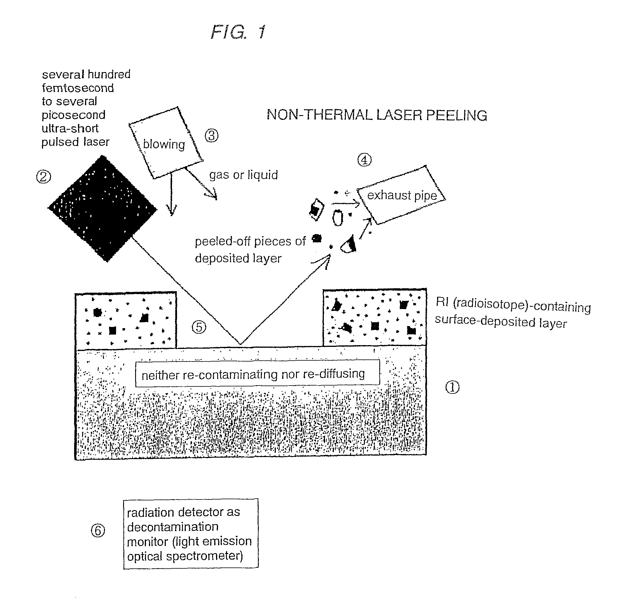
[0030][FIG. 1]

[0031]1: stainless steel-made non-radioactive structural component

[0032]2: several hundred femtosecond to several picosecond, ultra-short pulsed non-thermal laser

[0033]3: nozzle for blowing a fluid such as highly pressurized, carrying gas and liquid

[0034]4: exhaust pipe for inhaling peeled-off pieces of the surface-deposited layer

[0035]5: stainless steel-made interface that is free of a molten portion, as well as re-contaminating and re-diffusing

[0036]6: light emission optical spectrometer or radiation detector for monitoring the decontamination factor.
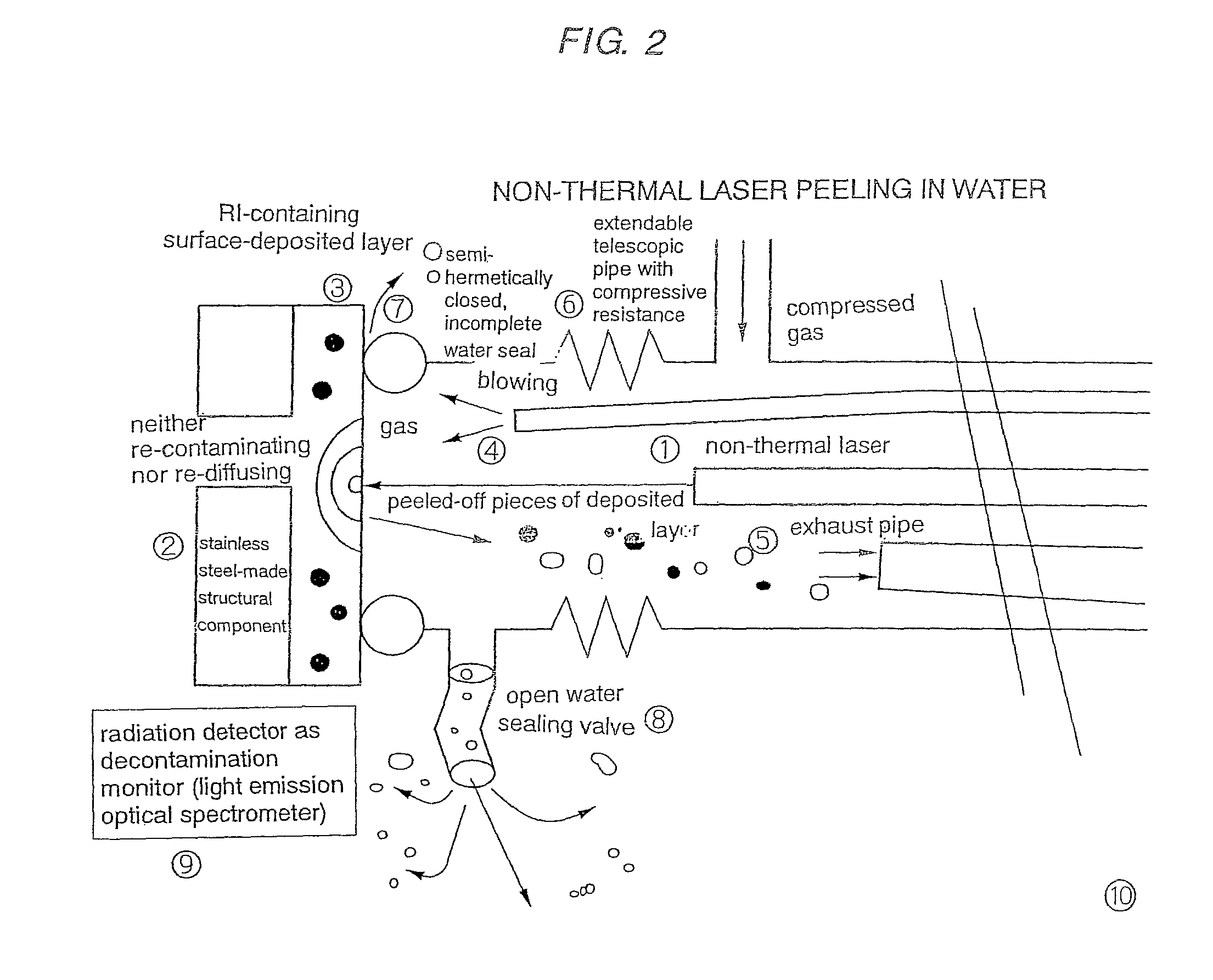
[0037][FIG. 2]

[0038]1: non-thermal laser

[0039]2: stainless steel structural component

[0040]3: RI-containing, surface-deposited layer

[0041]4: carrying fluid and a blow-off pipe for RI-removal

[0042]5: exhaust pipe for inhaling peeled-off pieces of the RI-containing, surface-deposited layer

[0043]6: extendable telescopic pipe with compressive resistance

[0044]7: semi-hermetically closed, incomplete water seal

[0045]8: open wat...


PUM

PropertyMeasurementUnit
pressureaaaaaaaaaa
light emission optical spectrometeraaaaaaaaaa
areaaaaaaaaaaa

Abstract

An apparatus with which areas near surfaces in a water environment that are contaminated by radioisotopes are decontaminated by non-thermal laser peeling without suffering re-melting, re-diffusing and re-contaminating. The apparatus includes a piping structure with which a substance to be irradiated that has been deposited on outer and inner surfaces of a nuclear reactor pressure vessel, and a nuclear reactor container tank, and the internal nuclear reactor structures all having been contaminated with radioisotopes, can be removed in the water environment. The piping structure, to secure a region in a water environment that is gas pressurized to discharge the water and filled with the gas to not interfere with laser irradiation, has a semi-hermetically closed, incomplete water seal that is half-open with a siphon provided downward, a mechanical structure that withstands water pressure in a radial direction, and an extendable bellows-like tube to enable the piping structure to tilt.

Description

CROSS-REFERENCE TO RELATED APPLICATIONS[0001]This application is a U.S. divisional application filed under 37 C.F.R. 1.53(b) claiming priority benefit of U.S. application Ser. No. 12 / 086,387, filed Jun. 12, 2008 now U.S. Pat. No. 8,097,765, allowed. This application also claims the benefit under 35 U.S.C. Section 371, of International Application No. PCT / JP2007 / 060872, filed May 29, 2007, which claimed priority to Japanese Application No. 2006-147918, filed May 29, 2006 in Japan, the contents of which are incorporated herein by reference.BACKGROUND[0002]1. Field[0003]This invention relates to a method by which areas near the surfaces of apparatuses that are contaminated by many kinds of radioisotopes as the result of handling many radioisotopes in the neighborhood of accelerators, nuclear reactors, RI product manufacturing factories, nuclear fuel factories, nuclear fuel reprocessing factories, etc. are decontaminated by non-thermal laser peeling without suffering re-melting, re-diff...

Claims


Application Information

Patent Timeline
Patent Type & Authority Patents(United States)
IPC IPC(8): G21C1/00G21F9/28
CPCB23K26/0635B23K26/1405G21F9/28Y10S588/90B23K26/142B23K26/0624
Inventor MINEHARA, EISUKE
Owner JAPAN ATOMIC ENERGY AGENCY INDEPENDANT ADMINISTRATIVE CORP
Why Eureka
Try Eureka