Ammonia injection grid for a selective catalytic reduction system

a catalytic reduction and ammonia injection technology, applied in the direction of machines/engines, separation processes, lighting and heating apparatus, etc., can solve the problems of high cost, inability to meet the requirements of long distance, etc., to achieve the effect of increasing the mixing efficiency of the ammonia injection grid

Active Publication Date: 2011-09-13
CALLIDUS TECH
View PDF16 Cites 41 Cited by
  • Summary
  • Abstract
  • Description
  • Claims
  • Application Information

AI Technical Summary

Benefits of technology

[0015]Each nozzle of the ammonia injection grid may form an approximate 75 degree angle relative to the upstream flow of flue gas. Further, the ammonia injection grid comprises a plurality of ammonia injection grid panels, such as at least one upper ammonia injection grid panel and at least one lower injection grid panel. The ammonia injection grid can also include an upper header and a lower header in fluid communication with the injection tube for supplying ammonia to the injection tube. The upper header and the lower header may be provided with a substantially V-shaped baffle plate to further increase the mixing efficiency of the ammonia injection grid. The substantially V-shaped baffle plate of the upper header and the lower header may form an approximate 44 degree angle relative to the flow of flue gas. The ammonia injection grid may include a nozzle in the upper header and a nozzle in the lower header, wherein the nozzle of the upper header and the nozzle of the lower header inject ammonia substantially perpendicular to the flow of flue gas.

Problems solved by technology

The catalysts used in SCR systems are carefully engineered and expensive.
Shortening the distance between the injection point and the catalyst is often desirable, and in new constructions a long distance is often unavailable due to a limited footprint for the ductwork.
In a retrofit application, a long distance may require cost prohibitive modifications to the existing system.
Static mixers typically utilize elaborate designs, high fabrication, and installation cost, along with resulting in a significant pressure drop.
While these known local baffles and deflectors installed between the injection tubes of ammonia injection grids increase the mixing efficiency, none provide for even distribution of ammonia to a downstream SCR catalyst for heat recovery, steam generation systems, packaged boilers, simple cycle catalyst systems, and fired heaters.

Method used


Image

  • Ammonia injection grid for a selective catalytic reduction system
  • Ammonia injection grid for a selective catalytic reduction system
  • Ammonia injection grid for a selective catalytic reduction system

Examples


Embodiment Construction

[0029]The devices and methods discussed herein are merely illustrative of specific manners in which to make and use this invention and are not to be interpreted as limiting in scope.

[0030]While the devices and methods have been described with a certain degree of particularity, it is to be noted that many modifications may be made in the details of the construction and the arrangement of the devices and components without departing from the spirit and scope of this disclosure. It is understood that the devices and methods are not limited to the embodiments set forth herein for purposes of exemplification.

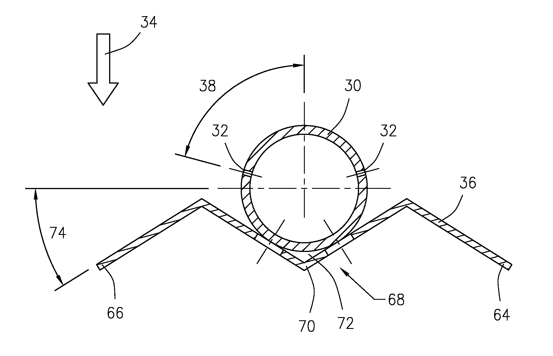
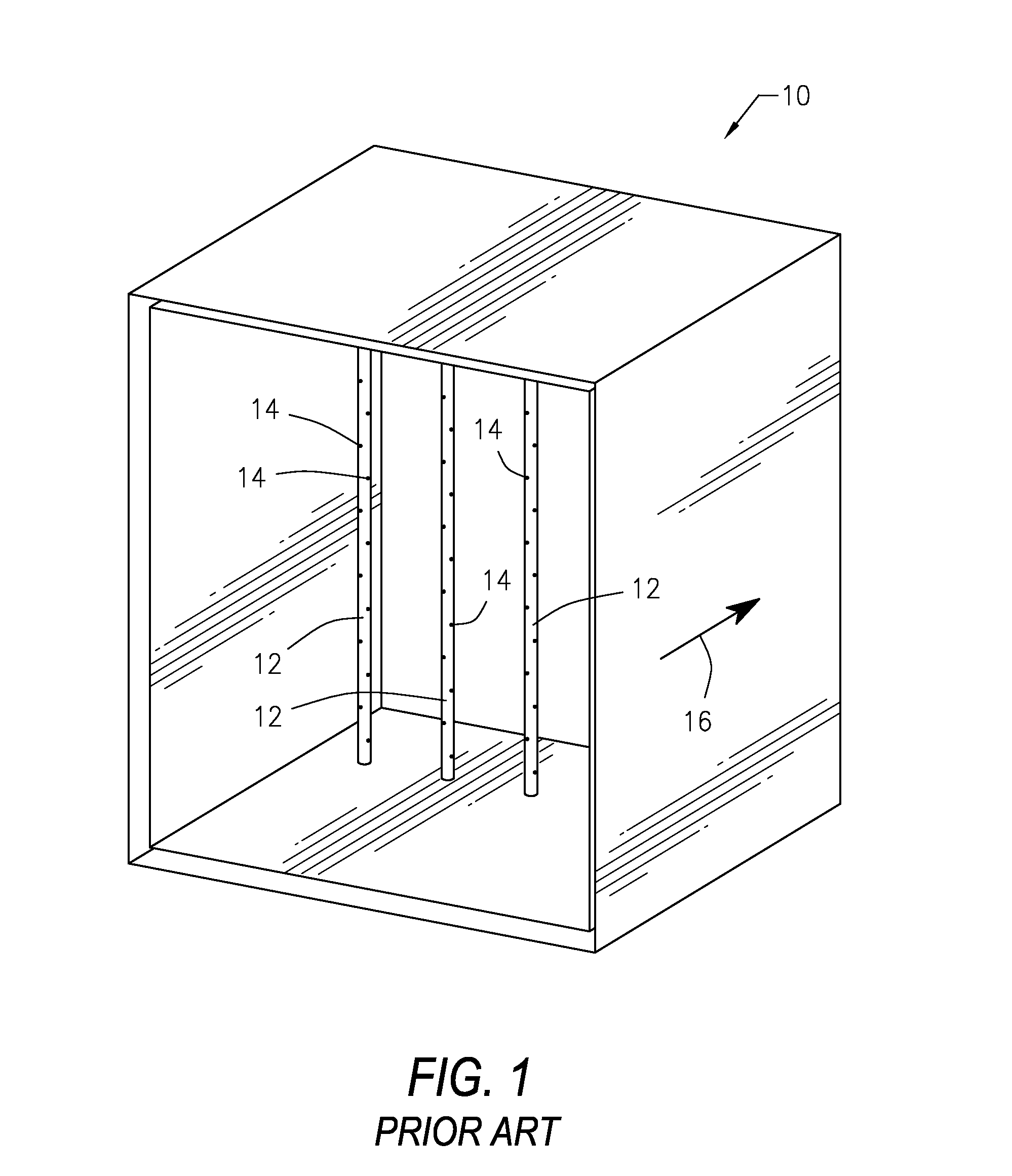
[0031]Referring to the figures of the drawings, FIG. 1 is a perspective view of a prior art ammonia injection grid (AIG) 10 utilizing a plurality of circular injection tubes 12 having a plurality of injection nozzles 14 angled forty-five (45) degrees upstream relative to the flow of flue gas 16. The AIG 10 is upstream of the SCR catalyst (not shown). The injection nozzles 14 along th...


PUM

PropertyMeasurementUnit
upstream angleaaaaaaaaaa
angleaaaaaaaaaa
angleaaaaaaaaaa

Abstract

An ammonia injection grid for a selective catalytic reduction (SCR) system that provides uniform distribution of ammonia to the SCR catalyst in NOx reduction systems for heat recovery steam generation systems, packaged boilers, simple cycle catalyst systems and fired heaters for superior operational efficiency. The ammonia injection grid includes an injection tube having at least one nozzle for injecting ammonia into a flow of flue gas. The ammonia injection grid also includes a corrugated turbulence enhancer associated with the injection tube to generate turbulent wake to enhance turbulent mixing.

Description

FIELD OF THE INVENTION[0001]This invention relates generally to an ammonia injection grid for a selective catalytic reduction (SCR) system, and more particularly to an ammonia injection grid for a SCR system that provides uniform distribution of ammonia to the SCR catalyst in NO reduction systems for heat recovery steam generation systems, packaged boilers, simple cycle catalyst systems and fired heaters for superior operational efficiency.DESCRIPTION OF THE RELATED ART[0002]NO refers to the cumulative emissions of nitric oxide (NO), nitrogen dioxide (NO2) and trace quantities of other chemicals during combustion which are environmentally hazardous substances. Combustion of fossil fuels generates some level of NO, due to high temperatures and availability of oxygen and nitrogen from both the fuel and air. NO emissions may be controlled using low NO combustion technology and postcombustion techniques, such as selective catalytic reduction (SCR). SCR systems catalytically reduce flue ...

Claims


Application Information

Patent Timeline
Patent Type & Authority Patents(United States)
IPC IPC(8): B01D53/90
CPCB01F3/04049B01F5/0451B01F5/0456B01F5/0463B01F5/0616B01F5/0618F23J15/003B01D53/9431B01D2251/2062B01F2005/0623B01F2005/0626F01N3/2066F01N3/2892F23J2219/10B01F23/2132B01F25/31322B01F25/31331B01F25/3131B01F25/4315B01F25/4316B01F25/43162B01F25/43172
Inventor WIRT, JEFFREY PHILIPMARTIN, RICHARD
Owner CALLIDUS TECH
Why Eureka
Try Eureka