RFID tags having ferromagnetic patches
a technology of ferromagnetic patches and rfid tags, which is applied in the direction of burglar alarm mechanical actuation, burglar alarm by hand-portable articles removal, instruments, etc., can solve the problems of antenna material and manufacturing costs, overall cost, and major obstacle in the cost of rfid tags
- Summary
- Abstract
- Description
- Claims
- Application Information
AI Technical Summary
Benefits of technology
Problems solved by technology
Method used
Image
Examples
example 1
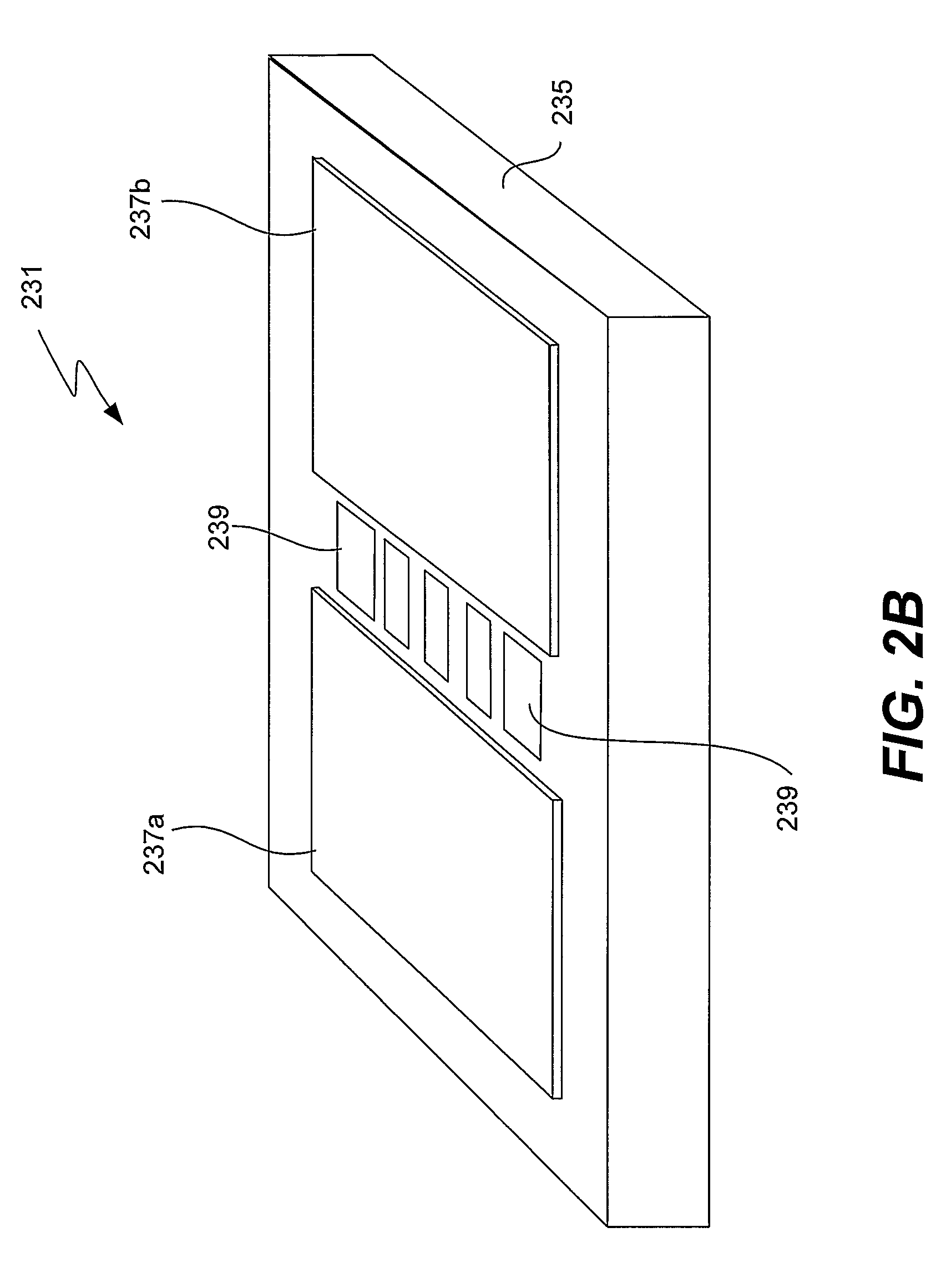
[0078]FIG. 8 shows a prototype ferromagnetic RFID device. As depicted, the device 801 includes a polytetrafluoroethylene (Teflon®) substrate 803 on which were attached two permanent magnets 805a and 805b, and two ferromagnetic islands 807a and 807b. Permanent magnets 805a and 805b were positioned to straddle the islands in order to provide a homogeneous magnetic field in the region of the islands. The magnets were rectangular pieces of NdFeB coated by Ni—Cu—Ni alloy purchased from Amazing Magnet, Irvine, Calif. and cut to dimensions of ½″×½″× 1 / 16″. They were separated from one another by a distance of 6 mm and attached to substrate 803 by double-sided type. Island 807a was a 4 mm×2 mm×0.075 mm slice of undoped YIG, and island 807b was a 2 mm×1 mm×0.45mm slice of gallium-doped YIG. The YIG material for the islands was purchased from Ferrite Domen Co, Russia.
[0079]Prototype device 801 was exposed to a scanning interrogation at frequencies of between approximately 1.7 GHz and 3.7 GHz ...
example 2
[0080]In this example, a series of ferromagnetic samples was prepared and tested for absorption. FIG. 10 presents a table of different ferromagnetic materials purchased from Ferrite Domen Co. Islands of these materials were cut from the purchased samples and then attached to a Teflon® substrate next to a permanent magnet. The field strength experienced by the samples was 69.4 mTesla. The vendor descriptions of the materials, as well as their dimensions in the test devices, the calculated absorption frequencies (independent of dimensions), and measured absorption frequencies are presented in the table of FIG. 10. The calculations of the resonance frequencies of the slabs and the films were performed using the demagnetization factor of an ideal thin film.
ƒ=γ√{square root over (B0·(B0+μ0M))} / (2π)
[0081]Ideally, the absorption frequency of each island would be a function of only material and the magnetic field strength (which is identical for each island in a well designed device). Howev...
PUM
 Abstract
Description
Claims
Application Information
 - R&D
- Intellectual Property
- Life Sciences
- Materials
- Tech Scout
- Unparalleled Data Quality
- Higher Quality Content
- 60% Fewer Hallucinations
Browse by: Latest US Patents, China's latest patents, Technical Efficacy Thesaurus, Application Domain, Technology Topic, Popular Technical Reports.
© 2025 PatSnap. All rights reserved.Legal|Privacy policy|Modern Slavery Act Transparency Statement|Sitemap|About US| Contact US: help@patsnap.com


