
Apparatus and method for cooperative relay in a wireless communication system based on relay stations

a wireless communication system and cooperative relay technology, applied in the field of cooperative relay in a multipleantenna wireless communication system, can solve the problems of reducing spectral efficiency, increasing thin realization of signal, etc., and achieve the effect of improving the reliability of signal transmission and maximizing throughpu

Active Publication Date: 2011-09-13
SAMSUNG ELECTRONICS CO LTD +1
View PDF6 Cites 214 Cited by
  • Summary
  • Abstract
  • Description
  • Claims
  • Application Information

AI Technical Summary

Benefits of technology

The present invention provides an apparatus and method for cooperative relay in a multiple-antenna wireless communication system based on relay stations (RSs). The technical effects of the invention include improving signal transmission reliability and maximizing throughput by providing an apparatus and method for cooperative relay that can divide data into N number of streams, calculate a first transmission rate at which each RS performing the cooperative relay can perform decoding and a second transmission rate at which RSs performing the cooperative relay can commonly perform decoding, and determine transmission rates of the N-number streams. The invention also includes a reception apparatus for cooperative relay that decodes a common signal in a received signal, removes the decoded common signal, and decodes the private signal. The invention provides a solution for improving the reliability and throughput of signal transmission in a multiple-antenna wireless communication system.

Problems solved by technology

Although multiple input multiple output (MIMO) technology has many merits, the chance of its realization is thin because of cost or hardware limitation.
Thus, the conventional art has a problem in that the reliability of signal transmission increases but a spectral efficiency decreases or, inversely, a spectral efficiency increases but the reliability of signal transmission is not guaranteed.

Method used


Image

  • Apparatus and method for cooperative relay in a wireless communication system based on relay stations
  • Apparatus and method for cooperative relay in a wireless communication system based on relay stations
  • Apparatus and method for cooperative relay in a wireless communication system based on relay stations

Examples


Embodiment Construction

[0027]FIGS. 1 through 8, discussed below, and the various embodiments used to describe the principles of the present disclosure in this patent document are by way of illustration only and should not be construed in any way to limit the scope of the disclosure. Those skilled in the art will understand that the principles of the present disclosure may be implemented in any suitably arranged wireless communication system.

[0028]An apparatus and method for cooperative relay for improving the reliability of signal transmission and maximizing throughput according to an exemplary embodiment of the present invention are described below.

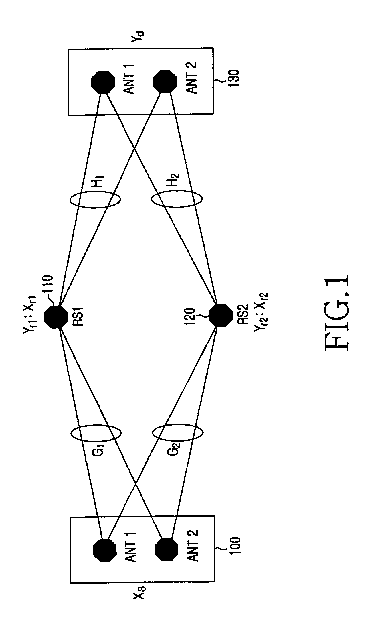
[0029]FIG. 1 is a diagram illustrating an example of a scenario of transmission / reception by each node in a multiple-antenna wireless communication system based on relay stations (RSs) according to an exemplary embodiment of the present invention.

[0030]In FIG. 1, there are a source node 100, two relay stations (RSs) 110 and 120, and a destination node 130 in t...


PUM


Abstract

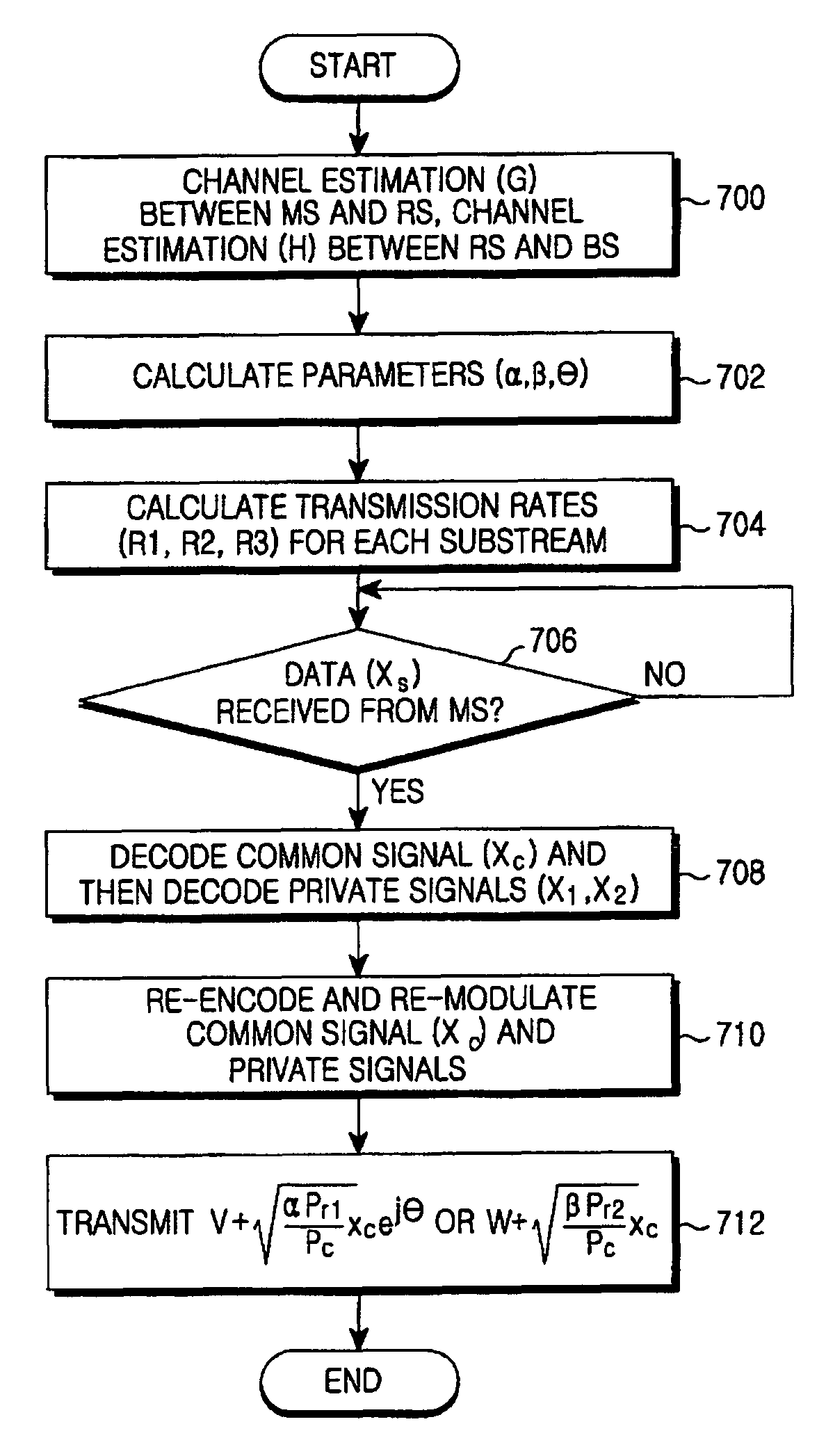
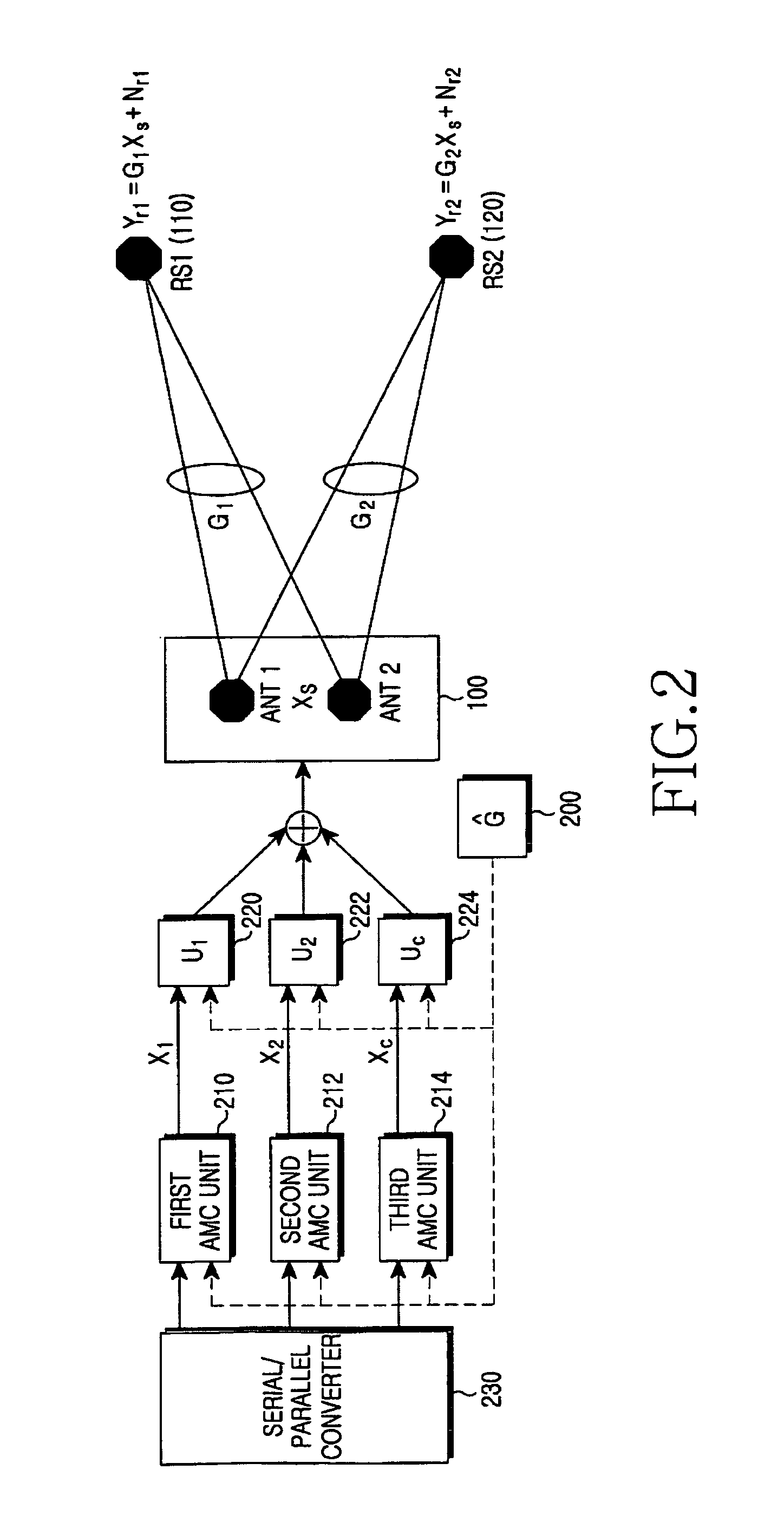
An apparatus and method for cooperative relay in a multiple-antenna wireless communication system based on relay stations (RSs) are provided. The apparatus includes a serial / parallel converter for dividing data into N number of streams, a channel estimator for calculating a first transmission rate at which a RS performing the cooperative relay can perform decoding and a second transmission rate at which all relay stations performing the cooperative relay can commonly perform decoding, and determining transmission rates for each of the N-number streams, and an adaptive modulation and coding (AMC) unit for encoding and modulating the N-number streams according to their respective transmission rates.

Description

CROSS-REFERENCE TO RELATED APPLICATION(S) AND CLAIM OF PRIORITY[0001]This application claims priority under 35 U.S.C. §119(a) to a Korean Patent Application filed in the Korean Intellectual Property Office on Aug. 14, 2007 and assigned Serial No. 2007-81770, the contents of which are herein incorporated by reference.TECHNICAL FIELD OF THE INVENTION[0002]The present invention relates generally to an apparatus and method for cooperative relay in a multiple-antenna wireless communication system based on relay stations (RSs) and, in particular, to an apparatus and method for cooperative relay for improving the reliability of signal transmission and maximizing throughput.BACKGROUND OF THE INVENTION[0003]An orthogonal transmission scheme, such as time division and frequency division, or a space time coding (STC) scheme, such as an Alamouti scheme, can be used to avoid interference among signals transmitted to each relay station (RS). These schemes designed in a single-antenna wireless com...

Claims


Application Information

Patent Timeline
Patent Type & Authority Patents(United States)
IPC IPC(8): H04B1/00H04B7/00
CPCH04B7/022H04B7/026H04B7/0617H04B7/15592H04W52/241H04L1/004H04L1/0009H04L1/0656H04L2001/0097H04L1/0003
Inventor YU, TAK-KIKIM, YUNG-SOOCHO, MYEON-KYUNCHUNG, SAE-YOUNGKIM, MURYONG
Owner SAMSUNG ELECTRONICS CO LTD
Learn More