
Sonic flow meter and method

Active Publication Date: 2011-09-13
BADGER METER
View PDF17 Cites 22 Cited by
  • Summary
  • Abstract
  • Description
  • Claims
  • Application Information

AI Technical Summary

Benefits of technology

[0005]Yet another feature is a start-up method for circuitry for conducting Doppler flow measurements which esta

Problems solved by technology

The measurement of flow of a liquid which may be contaminated with foreign particles or gas bubbles presents problems.

Method used


Image

  • Sonic flow meter and method
  • Sonic flow meter and method
  • Sonic flow meter and method

Examples


Embodiment Construction

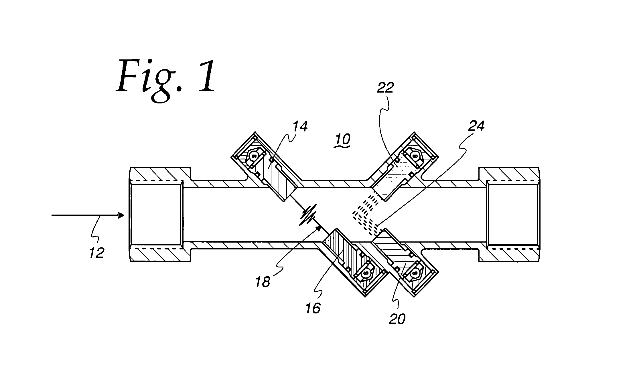
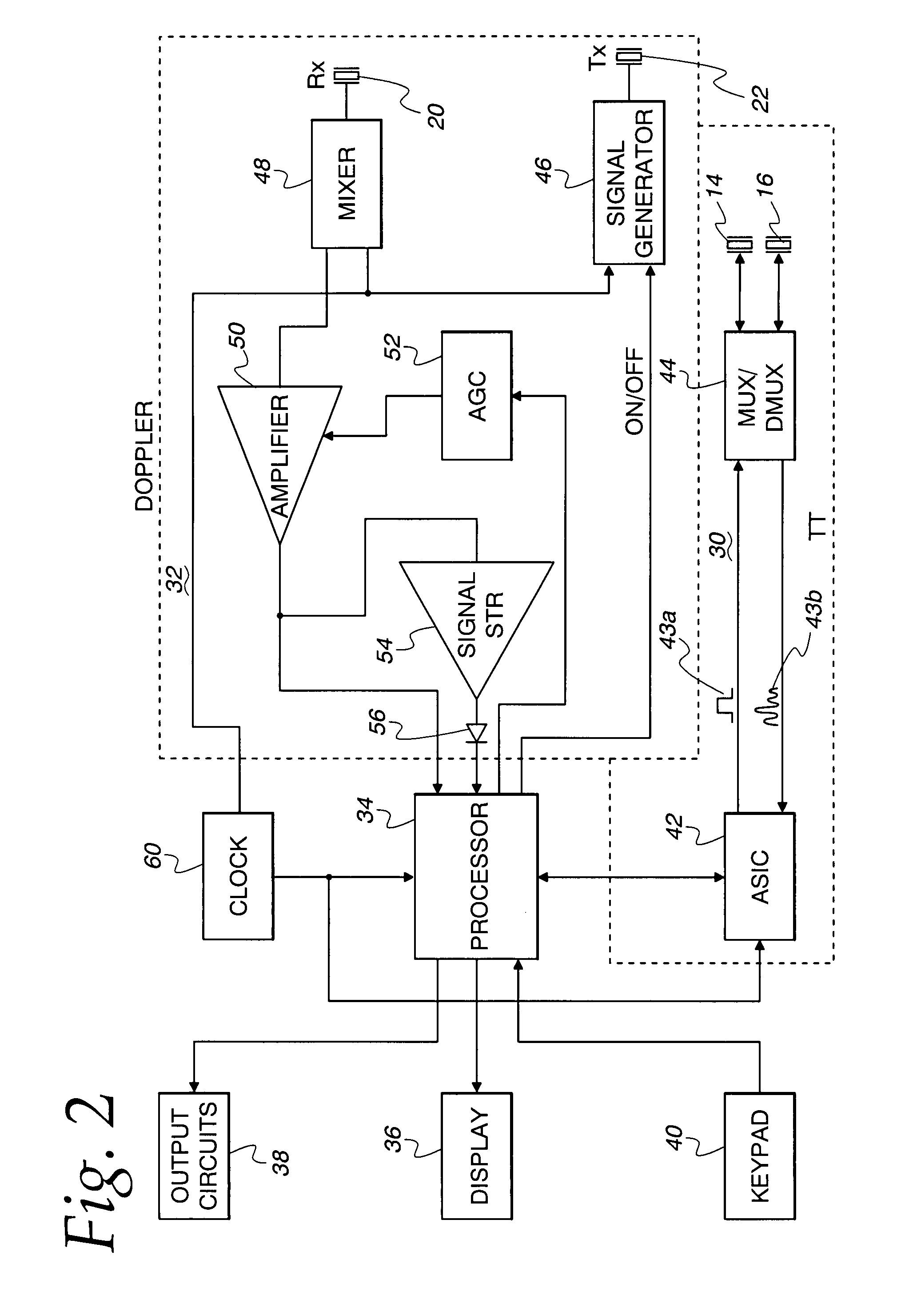
[0012]A pipe section 10, FIG. 1, serves as a housing for the transducers used in conducting the transit time and Doppler flow measurements. The pipe section 10 is connected in the pipe line for the flow of liquid to be measured with the primary flow direction as indicated by arrow 12. The transit time transducers 14, 16 are mounted in alignment on opposite sides of the housing with a signal path 18 between them, at an angle of the order of 45 degrees to the pipe axis. When the transducer 14 serves as transmitter and transducer 16 as receiver, the sonic signal travels downstream with the liquid flow and transit time is reduced. When the transducer 16 serves as transmitter and transducer 14 as receiver, the sonic signal travels upstream against the liquid flow and transit time is increased. Doppler transducers 20, 22 are both directed toward the center of housing 10. The signal from transmitting transducer 22 is reflected to receiving transducer 20 along signal path 24 by bubbles or p...


PUM


Abstract

A flow meter and method for measuring flow in liquids which may have entrained bubbles or foreign matter. The meter performs alternate transit time and Doppler measurements. The transit time measurements are used to calculate flow so long as they are successful. If the transit time measurements are not successful, the Doppler measurements are used.

Description

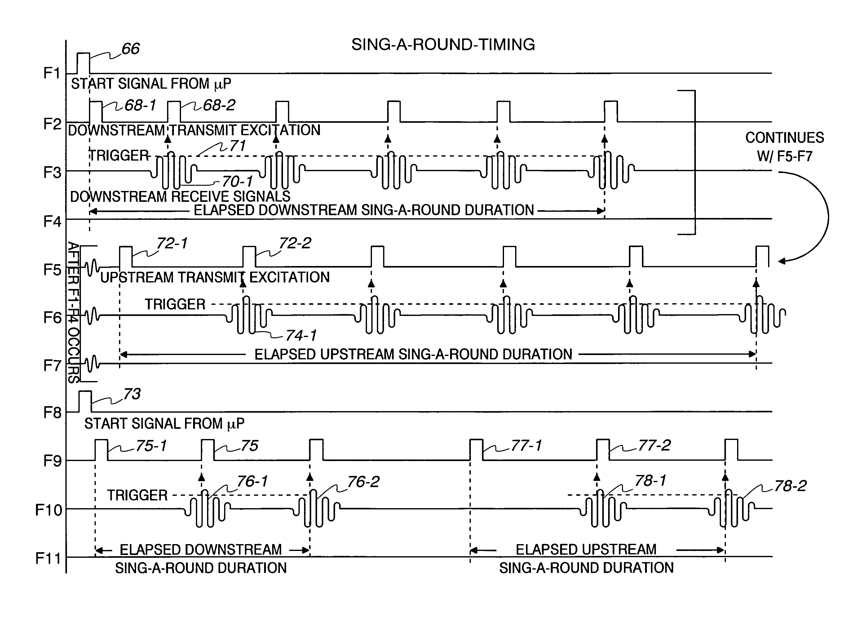
BACKGROUND OF THE INVENTION[0001]The measurement of flow of a liquid which may be contaminated with foreign particles or gas bubbles presents problems. Transit time measurements provide accurate flow measurement of uncontaminated liquid. However, when the liquid is contaminated, Doppler measurement provides more reliable flow measurement. For example, water pumped from the ground during the production of methane gas from a coal seam or other underground shale varies from crystal clear to milky white with entrained methane. Many applications also have intermittent suspended particulates of coal, rocks or sand in the water. Dual mode meters are known, see Oldenziel et al. U.S. Pat. No. 5,533,408, Shekarriz et al. U.S. Pat. No. 6,067,861, Morgen et al. U.S. Pat. No. 6,871,148, and Ishikawa published application 2006 / 0174717.BRIEF SUMMARY OF THE INVENTION[0002]The meter and method of this invention perform alternate periods of transit time and Doppler measurements. Transit time measurem...

Claims


Application Information

Patent Timeline
IPC IPC(8): G01F1/66G06F17/40
CPCG01F1/662G01F1/663G01F1/667G01F1/74G01F25/003G01F25/13
Inventor STEVENS, ROBERT K.LITTLE, RICHARD L.ROEBER, WILLIAM W.
Owner BADGER METER
Learn More