Self-raising form control system and method

a control system and self-raising technology, applied in the field of self-raising form control system and method, can solve the problems of inability to control the lifting of the entire lift apparatus, inconvenient operation, and inability to accurately read the reading, and achieve the effect of enhancing the hydraulically lifted concrete form system and being precis

Active Publication Date: 2011-09-20
FORMING CONCEPTS INC
View PDF26 Cites 9 Cited by
  • Summary
  • Abstract
  • Description
  • Claims
  • Application Information

AI Technical Summary

Benefits of technology

[0011]The invention provides a form control and monitoring system that coordinates the raising of form elements by lift apparatus so that the form elements are lifted in a closely controlled, automatic manner. The lift apparatus includes plural lifting devices wherein the extent of lifting at each device is closely controlled with respect to the other lifting devices. This close control can be used to ensure a precise, even lifting of the entire lift apparatus. The control and monitoring system of the invention particularly enhances hydraulically lifted concrete form systems such as used for elevator cores.

Problems solved by technology

In leveling these hydraulically lifted concrete forms from floor to floor, several systems are presently used, and they each have significant drawbacks.
The problems with water levels are that they must be maintained and serviced prior to every lift to be sure they are operational.
Often times the operator will ignore or not be aware of variances that can be critical to the loading of major form components creating an unsafe condition.
The water lines used in a water leveling system can often become kinked and / or clogged causing the readings to be incorrect.
Because of the length of the water lines and the routing that often times must be taken, the lines are prone to damage.
All these factors contribute to inaccuracy in the lifting process.
The system is very labor intensive and inaccurate requiring many men to measure at once and is only as accurate as the men doing the physical measurement and the ability of the operator to analyze the information and respond quickly to it.
This method is the most inaccurate since no actual measuring devices are used.
This is often not true because the equipment used cannot guarantee repeatability.
For instance, there may be leakage in the system or there may be variances in the construction of the items employed in the lift.

Method used


Image

  • Self-raising form control system and method
  • Self-raising form control system and method
  • Self-raising form control system and method

Examples


Embodiment Construction

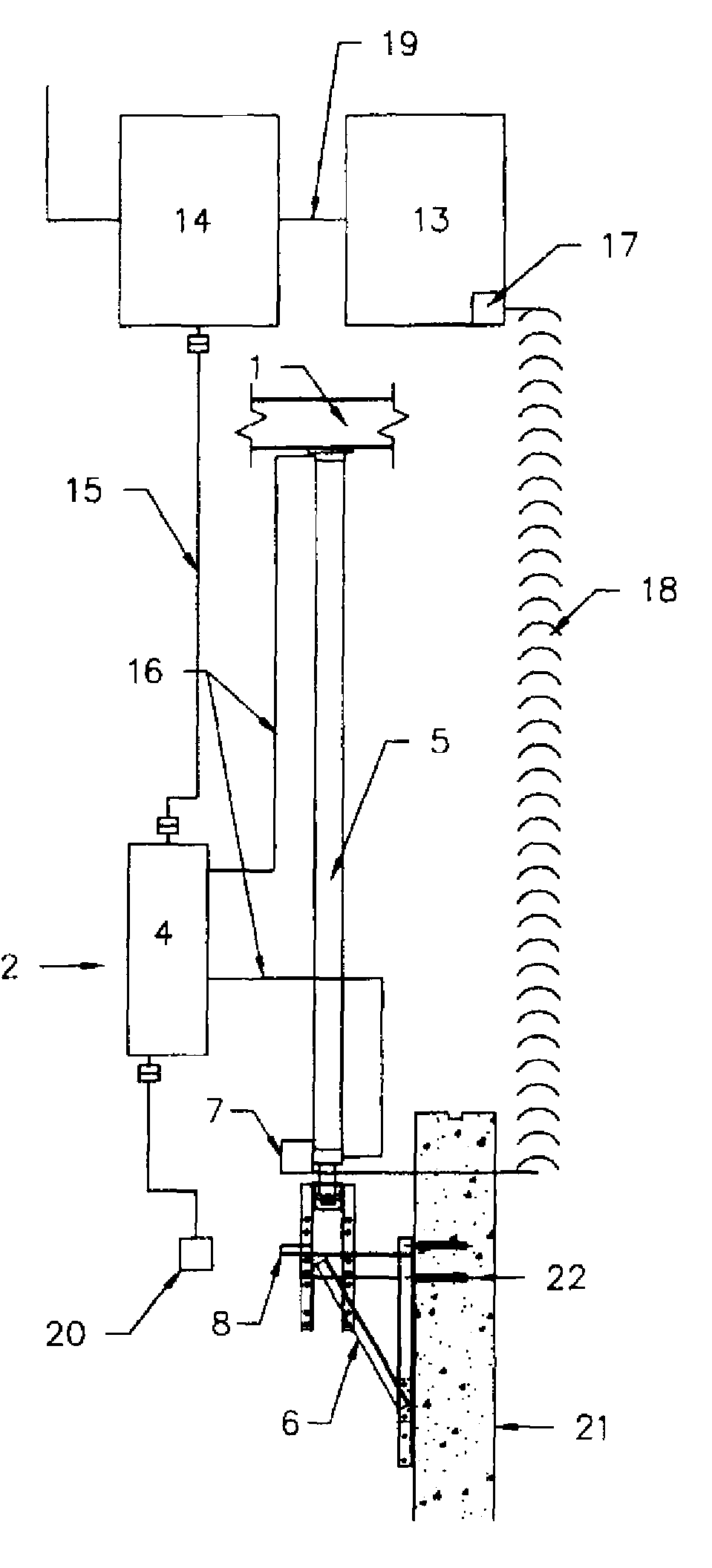
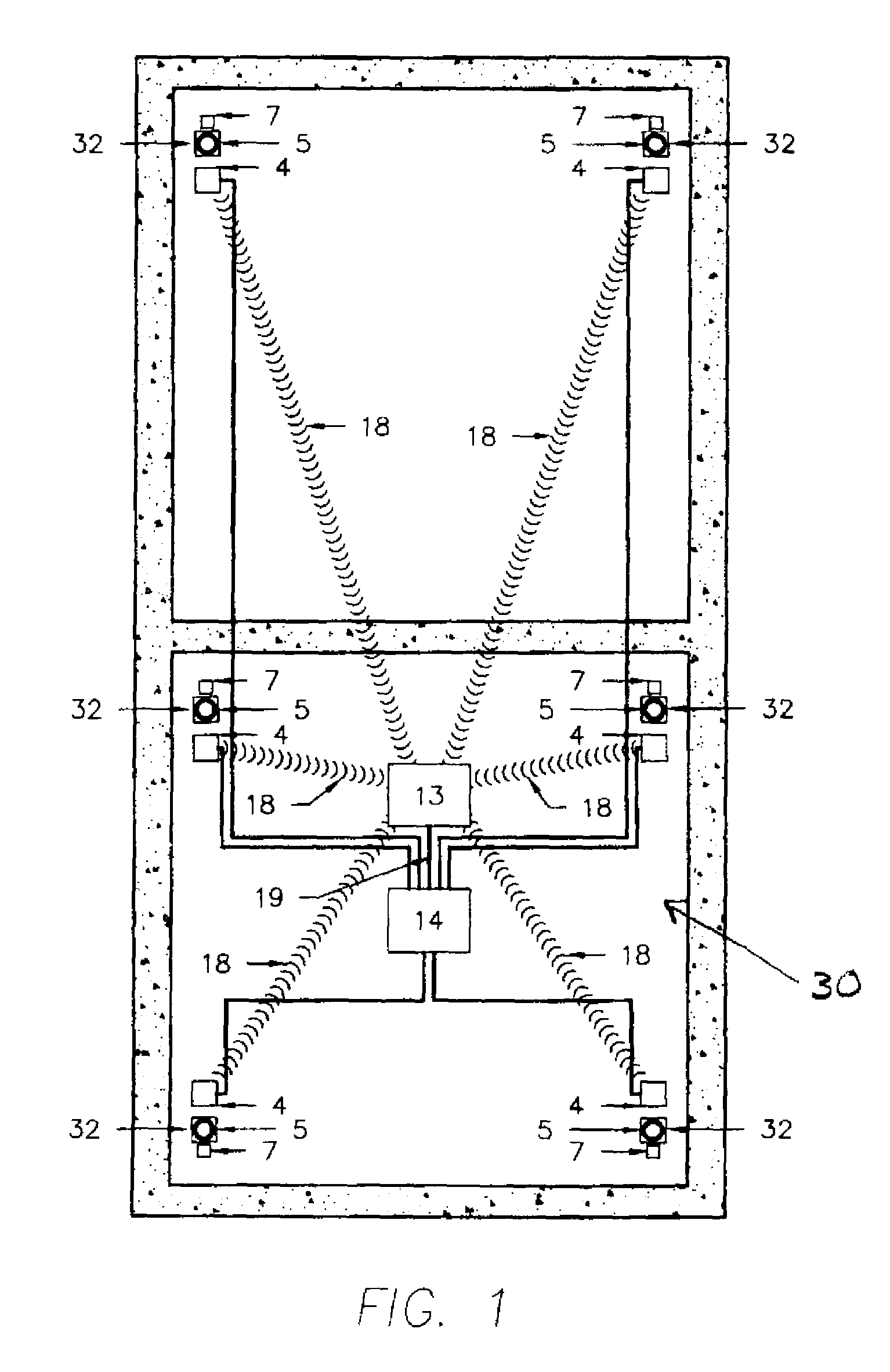
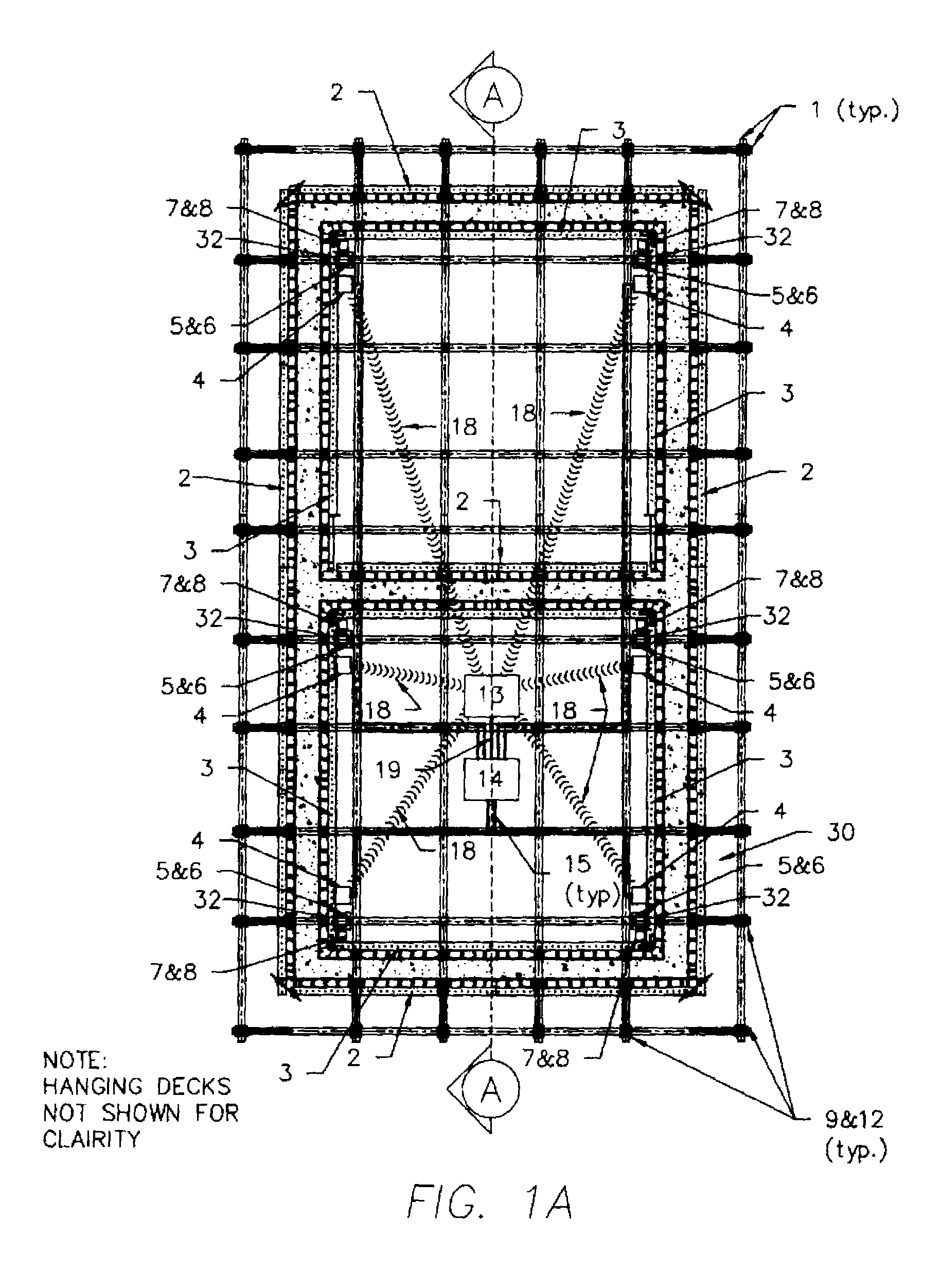
[0030]Referring to FIGS. 1, 1A and 2, a self-raising form control system 30 of the present invention is illustrated in an initial set up position. Referring specifically to FIG. 2, it can be seen that the concrete for levels A through C have been poured and formed and that the form control system 30 has been put in place prior to extending the form for the next level (Level D). Deck levels 11 have been put in place on each level between the formed concrete. Outside hanging scaffolding 9, 12 has also been put in place to give personnel access to the concrete form assembly. The form control system 30, in this embodiment, includes a central control panel 13, a power control panel 14, a grid support beam 1 and a number of jack assemblies 32. In this embodiment, the form control system 30 includes six jack assemblies 32, as shown in FIG. 1A, which are attached to the grid support beam 1.

[0031]As shown in FIG. 2, the central control panel 13 and the power control panel 14 are connected to...


PUM

PropertyMeasurementUnit
Operating voltageaaaaaaaaaa
heightaaaaaaaaaa
lift heightaaaaaaaaaa

Abstract

A self-raising form control system and method is provided that that may be used to form elevator shafts and other vertical building structures. The apparatus includes one or more form elements for defining an area to receive a formable material, such as concrete. Each element is attached to the form structure. A lift apparatus is provided for lifting the form elements. The lift apparatus comprises a measurement device for measuring the position of said lift apparatus relative to a fixed point. The lift apparatus is connected to the form structure. A control unit is provided for controlling the lift apparatus. The control unit is signal connected to the measurement device and is signal connected to the lift apparatus.

Description

[0001]This application claims the benefit of U.S. provisional patent application Ser. No. 60 / 959,093 filed on Jul. 11, 2007.FIELD OF THE INVENTION[0002]The invention relates to systems for lifting a concrete forming structure or apparatus.BACKGROUND[0003]Hydraulically lifted concrete form systems for elevator cores are presently known and used on building construction sites. In leveling these hydraulically lifted concrete forms from floor to floor, several systems are presently used, and they each have significant drawbacks.[0004]The first known raising system utilizes water levels. The problems with water levels are that they must be maintained and serviced prior to every lift to be sure they are operational. The accuracy of the lift is determined by the operator of the system. The accuracy of how even the form is lifted is dependent on how quickly the water levels respond in the tubes and how quickly the operator responds to variances. Often times the operator will ignore or not b...

Claims


Application Information

Patent Timeline
Patent Type & Authority Patents(United States)
IPC IPC(8): B23Q17/00
CPCE04G11/22E04G11/24E04G11/28Y10T29/49764Y10T29/5303Y10T29/49771Y10T29/53039Y10T29/49623Y10T29/53026
Inventor BAUM, NORTONDZIEDZIC, JR., NORMAN JOHN
Owner FORMING CONCEPTS INC
Why Eureka
Try Eureka