High efficiency integrated automotive wheel

a high-efficiency, integrated technology, applied in the field of automotive wheels, can solve the problems of increasing the energy loss of tires, increasing the risk of collisions, and little has been done to remedy a serious source of wasted energy in vehicles, so as to reduce energy loss, improve rigidity, and reduce the effect of deformation

Inactive Publication Date: 2011-09-20
MORRISON GLENN ARTHUR
View PDF16 Cites 9 Cited by
  • Summary
  • Abstract
  • Description
  • Claims
  • Application Information

AI Technical Summary

Benefits of technology

[0020]The present device is an integrated automotive wheel for electric vehicles which substantially reduces energy loss due to tire flex and energy loss from a conventional drive train. An embodiment of the device includes a hub, two composite sidewalls, a low pressure inner chamber containing a hub protector, and a high pressure pneumatic outer ring with tread. An embodiment may include an electric hub motor which rotates the hub and tire, propelling the vehicle. The sidewalls contain at least one high pressure chamber which position the outer ring and enable the wheel to simulate an energy efficient high pressure pneumatic wheel, experiencing little deformation when under smooth road conditions. The outer ring and sidewalls can be filled with closed cell foam to prevent tire flats and improve stiffness. When road conditions are rough, the sidewalls can temporarily buckle in response to the increased road forces, simulating a conventional tire having ample space for deformation, with suspension and shock absorption capability built in. An embodiment can include one or more ring restraint bands in the low pressure chamber for better control of the restoring force on the outer ring when the outer ring is deformed. An embodiment can include an automatic device for maintaining the correct gas pressure in the low pressure chamber.

Problems solved by technology

Disadvantages were a hard ride and frequent punctures.
These tires involved greater energy loss mainly due to tire flex at and near the area of contact with the road.
However, little has been done to remedy a serious source of wasted energy in vehicles: the process of vehicle kinetic energy being converted to heat due to tire flex.
A small amount of tire flex occurs at or near the road contact, leading to low energy losses.
There is nothing present that enables simulation of the rigid support provided to a narrow high pressure tire by its rim.
Much of the outer chamber would move vertically in response to a road obstruction, possibly leading to an actual reduction in efficiency.
As a result the Lambe tire cannot truly and effectively simulate a high pressure pneumatic tire on a smooth road.
These devices serve to reduce damage to the hub and rim after a puncture, but are not designed to function as shock absorbers or suspensions.
The previous attempts at producing a tire design combining the advantages of energy conservation on smooth roads and cushioning on rough roads have proven inadequate.

Method used


Image

  • High efficiency integrated automotive wheel
  • High efficiency integrated automotive wheel
  • High efficiency integrated automotive wheel

Examples


Embodiment Construction

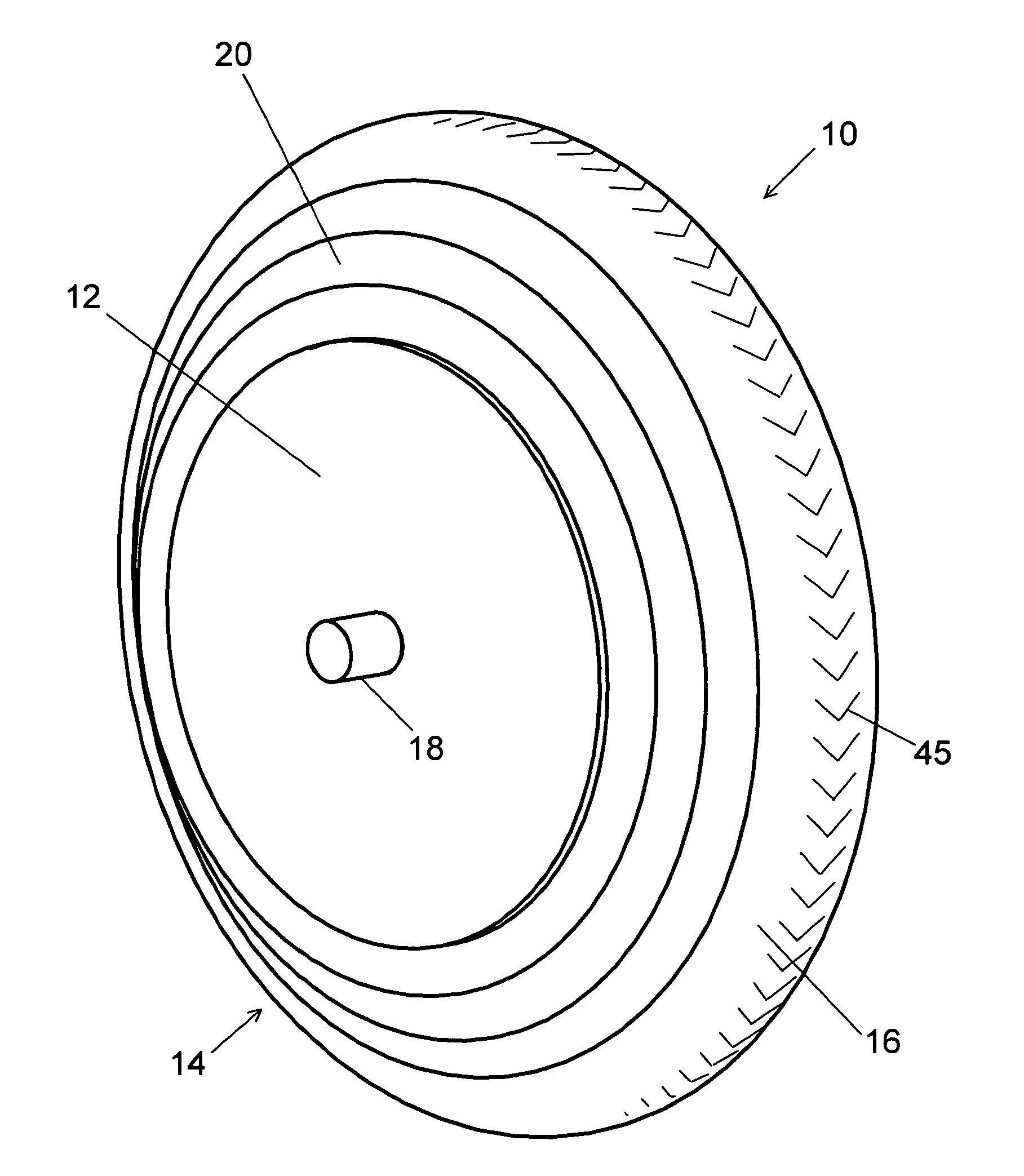
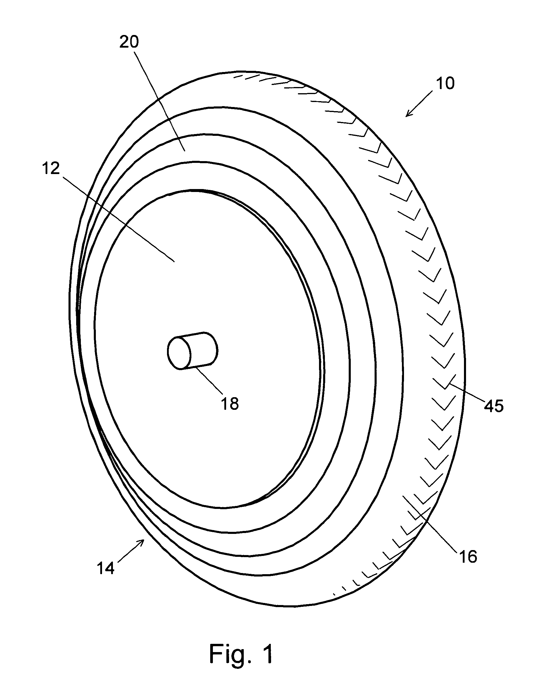
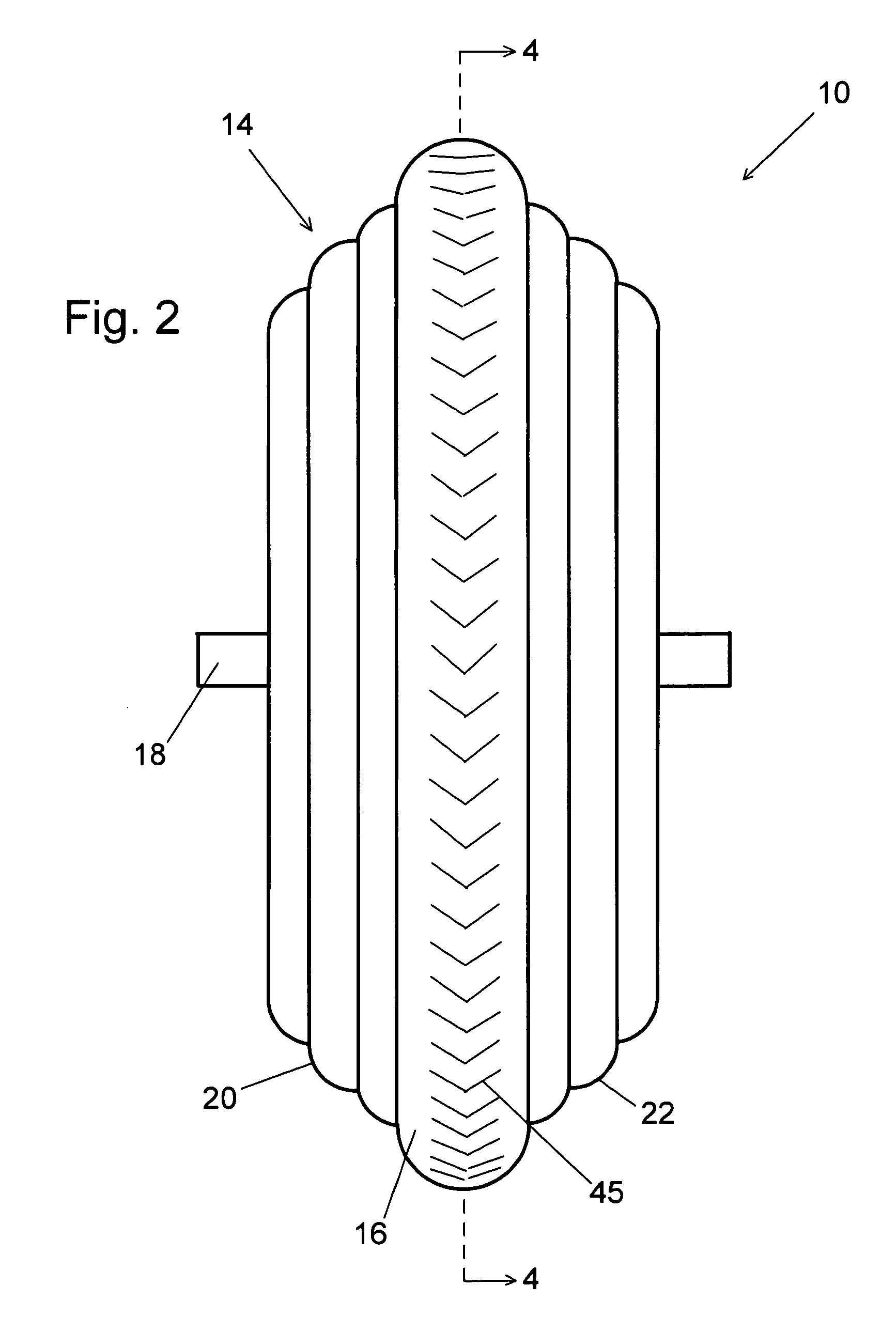
[0025]The integrated wheel 10 is an energy-efficient wheel for automotive use. It is an automotive wheel that performs like a high pressure bicycle wheel where the road is smooth and acts like a low pressure conventional cushioning wheel where the road is rough. To accomplish this goal, the present device incorporates a high pressure section for simulating a high pressure tire and a low pressure section which enables simulation of a cushioning tire. A conventional automotive suspension requires the entire wheel to move vertically in response to a road obstruction, generating a large kinetic energy that must be dissipated into heat by the suspension and shock absorber. The present device, on the other hand, requires only a local portion of the tire to deform, resulting in much less kinetic energy to be dissipated. When an electric hub motor is included in the present device, the weight of external wheel bearings and suspensions can be reduced, the conventional drive train and transmi...


PUM


Abstract

The present device is an integrated automotive wheel for electric vehicles which substantially reduces energy loss due to tire flex and energy loss from a conventional drive train. The wheel includes an axle, a hub, two composite sidewalls, a low pressure inner chamber with shock absorbing hub protector, and at least one outer high pressure pneumatic chamber with tread. The hub can contain an electric hub motor which rotates the wheel, propelling the vehicle. The sidewalls include at least one pressurized chamber which position the outer tread ring and enable the wheel to simulate an energy efficient high pressure pneumatic wheel, experiencing little deformation when under smooth road conditions. When road conditions are rough, the sidewalls can temporarily buckle in response to the increased road forces, simulating a low pressure conventional tire having ample space for deformation, with suspension and shock absorption capability built in. The sidewalls and outer ring chamber can be filled with high pressure closed cell foam to prevent flats.

Description

CROSS-REFERENCE TO RELATED APPLICATIONS[0001]The outer ring, hub protector and hub motor derive from the previous application of Ser. No. 11 / 769,566, filed 2007 Jun. 27, prepared by David J. Bremer, Reg. # 51497, for the present inventor.FEDERALLY SPONSORED RESEARCH[0002]Not ApplicableSEQUENCE LISTING OR PROGRAM[0003]Not ApplicableFIELD OF INVENTION[0004]The present invention relates to automotive wheels and, more particularly, to energy-efficient automotive wheels.BACKGROUND[0005]In the late 19th and early 20th centuries, the design of automotive wheels was based on that of bicycle tires, having thin walls with high pressure and narrow profiles. The advantage of this, important at that time, was high energy efficiency with low energy loss due to tire flex. Disadvantages were a hard ride and frequent punctures. As time went on, engines became more powerful and fuel became less expensive. Freedom from flats and ride comfort took top priority, leading to wider, lower pressure, thicker...

Claims


Application Information

Patent Timeline
Patent Type & Authority Patents(United States)
IPC IPC(8): B60C5/20B60C5/22B60C5/24
CPCB60B19/00B60C5/01B60C5/22B60C5/002Y10T152/10522Y10T152/10594B60C2200/12
Inventor MORRISON, GLENN ARTHUR
Owner MORRISON GLENN ARTHUR
Why Eureka
Try Eureka