Method for manufacturing dental prostheses, method for creating a data record and computer-readable medium

a technology for dental prostheses and data records, applied in dental surgery, instruments, teeth capping, etc., can solve the problems of high manufacturing cost, inability to achieve the precision desired for dental prostheses, and uneven surface, etc., and achieve the desired precision of dental prostheses. , the effect of rapid prototyping

Active Publication Date: 2011-09-20
INSTITUT STRAUMANN AG +1
View PDF35 Cites 31 Cited by
  • Summary
  • Abstract
  • Description
  • Claims
  • Application Information

AI Technical Summary

Benefits of technology

[0006]It is, for example, in particular avoided in the process that a tool of a machining method (e.g. a cutter head for milling) is occupied for a relatively long time with removing material which is far away from the surface of the dental prosthesis, so that removal can be essentially restricted to fine machining, which, however, can be performed relatively quickly.
[0018]Furthermore, an embodiment where a manufactured dental prosthesis is sintered after manufacture and before working is advantageous. Thereby, the shaping manufacturing process of the dental prosthesis can be completed and the exact desired shape can be manufactured. Distortion of the dental prosthesis by subsequent sintering is thus excluded. It is, however, also possible to first rework a dental prosthesis with a milling method and to subsequently subject it to dense sintering. This is in particular advantageous with respect to the wear of milling cutters which is comparably low in the working of not yet completely sintered materials.

Problems solved by technology

A disadvantage of this method is that normally step-like or very rough surfaces result from the application of material in layers and subsequent local sintering.
The precision desired for dental prostheses can often not be achieved.
In this process, however, material consumption can be considerable, so that the manufacture is cost-intensive.

Method used


Image

  • Method for manufacturing dental prostheses, method for creating a data record and computer-readable medium
  • Method for manufacturing dental prostheses, method for creating a data record and computer-readable medium
  • Method for manufacturing dental prostheses, method for creating a data record and computer-readable medium

Examples


Embodiment Construction

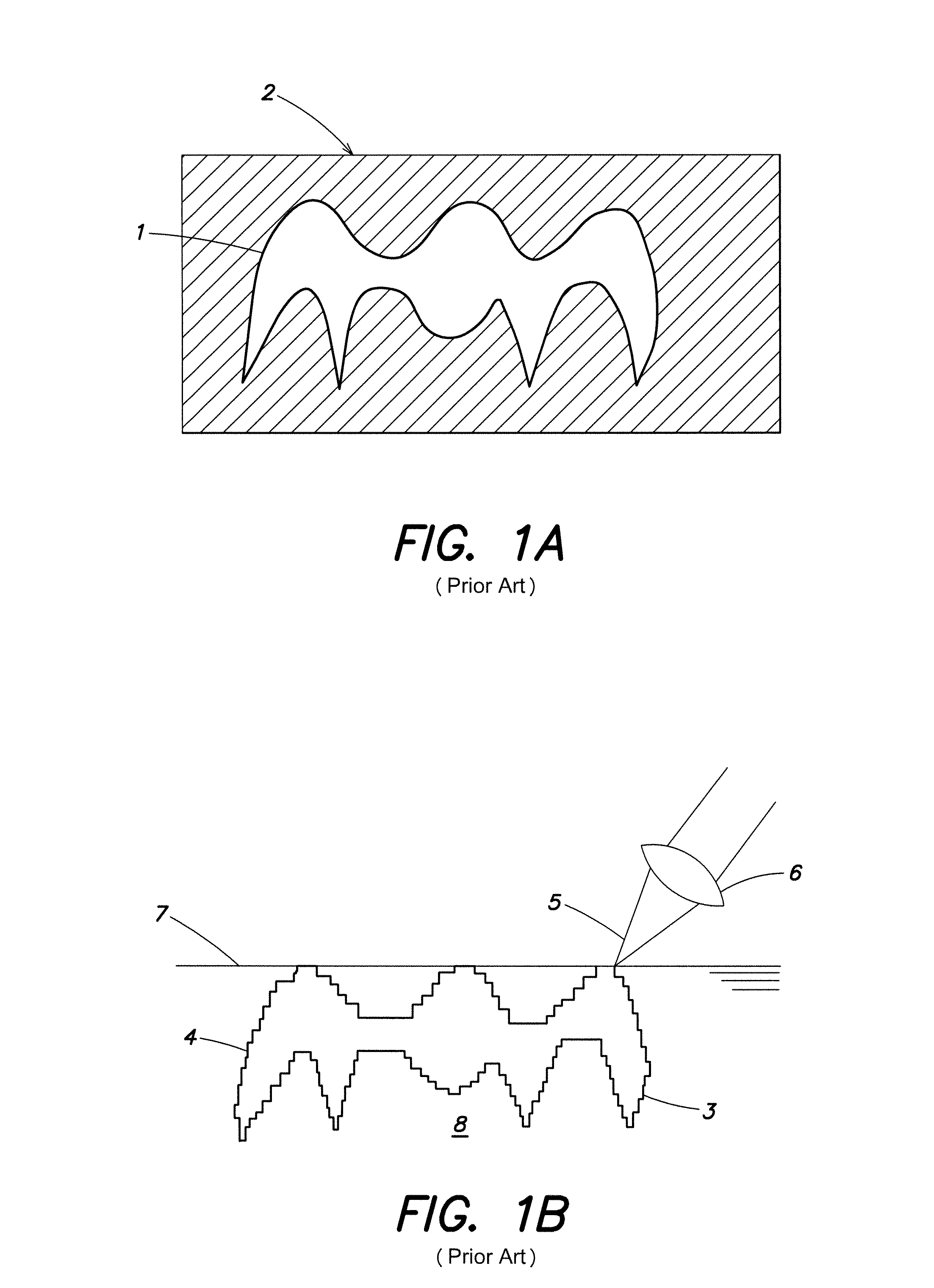
[0033]In FIG. 1a, a blank 2 from which a dental prosthesis 1 can be milled out is shown. For this, the complete shaded area of material has to be removed, which is relatively time consuming. With this milling method, it furthermore has to be taken into consideration that the portion of blank 2 which is not used for the dental prosthesis 1 is machined, that means it cannot be directly reused.

[0034]In FIG. 1b, an example of a rapid prototyping method is shown, in this case laser sintering. A powdery or liquid material is provided in area 8 which has been applied in layers, for example with a slider and locally melted (or otherwise modified) with a focused (see reference numeral 6) laser beam 5, so that it is subsequently solidified after cooling (or the like). The surface of the powder is marked with reference numeral 7.

[0035]In the section in FIG. 1b, the dental prosthesis 3 has a relatively high surface roughness 4. This is the result of the application of the material 8 to be solid...


PUM

PropertyMeasurementUnit
areaaaaaaaaaaa
surface roughnessaaaaaaaaaa
rough surfacesaaaaaaaaaa

Abstract

A method for manufacturing one or several dental prostheses, comprising the steps of: performing a rapid prototyping method for manufacturing one or several dental prostheses and subsequent working, such as reworking, of the one or several dental prostheses with a machining method, such as a milling method. In addition, a method for creating a data record which can be used for a rapid prototyping method for manufacturing a dental prosthesis wherein an end data record is obtained from a starting data record, so that in at least one area of a dental prosthesis manufactured with the end data record excess material is provided, compared to a dental prosthesis manufactured with the starting data record.

Description

FIELD OF THE INVENTION[0001]The invention relates to a method for manufacturing dental prostheses, a method for creating a data record as well as a computer-readable medium.BACKGROUND[0002]It is known from the prior art to manufacture dental prostheses for example by laser sintering. In the process, for example a metal powder is locally melted so that it solidifies upon cooling in the molten area. In this manner, a three-dimensional dental prosthesis can be manufactured by applying powder in layers and subsequently selectively sintering the same. A disadvantage of this method is that normally step-like or very rough surfaces result from the application of material in layers and subsequent local sintering. The precision desired for dental prostheses can often not be achieved.[0003]It is furthermore known from the prior art to mill dental prostheses out of solid material. By this method, dental prostheses of sufficiently high precision can be made. In this process, however, material c...

Claims


Application Information

Patent Timeline
Patent Type & Authority Patents(United States)
IPC IPC(8): A61C5/10A61C13/08G06F19/00A61C5/77
CPCA61C13/0013A61C13/0018A61C13/0019B33Y80/00B33Y50/00B33Y70/00
Inventor HOLZNER, STEPHANWEBER, GERHARD
Owner INSTITUT STRAUMANN AG
Why Eureka
Try Eureka