Device for measuring magnetic particles and corresponding method

a technology of magnetic particles and measuring devices, which is applied in the measurement of magnetic particles, instruments, magnetic separation, etc., can solve the problems of insignificant change in inductance, sensitivity of apparatus, asymmetry of coils, and magnetic particles, so as to achieve accurate measurement results, less sensitive, and easy to distinguish

Active Publication Date: 2011-09-27
DIASYS DIAGNOSTIC SYST +1
View PDF6 Cites 8 Cited by
  • Summary
  • Abstract
  • Description
  • Claims
  • Application Information

AI Technical Summary

Benefits of technology

[0013]By means of the device according to the invention, very accurate measurement results can be obtained, even in the case of very weak magnetic analytes. The high measuring frequencies applied in the measurement, and the differential coil construction mean that the device is eminently suitable for use at even room temperature, in terms of

Problems solved by technology

The application of traditional coil technology to such an arrangement, however, is associated with significant problems relating, for example, to the sensitivity of the apparatus.
Another problem can be mentioned the asymmetry of the coils, which is caused by, for example, the manual winding of the coils.
The magnetism of magnetic particles and thus the change in inductance they create in a coil system is very insignificant compared, for example, to the error signals caused by the environment or the test base itself.
Thus the measurement results obtained using the apparatus leave much to be desired.
In additi

Method used


Image

  • Device for measuring magnetic particles and corresponding method
  • Device for measuring magnetic particles and corresponding method
  • Device for measuring magnetic particles and corresponding method

Examples


second embodiment

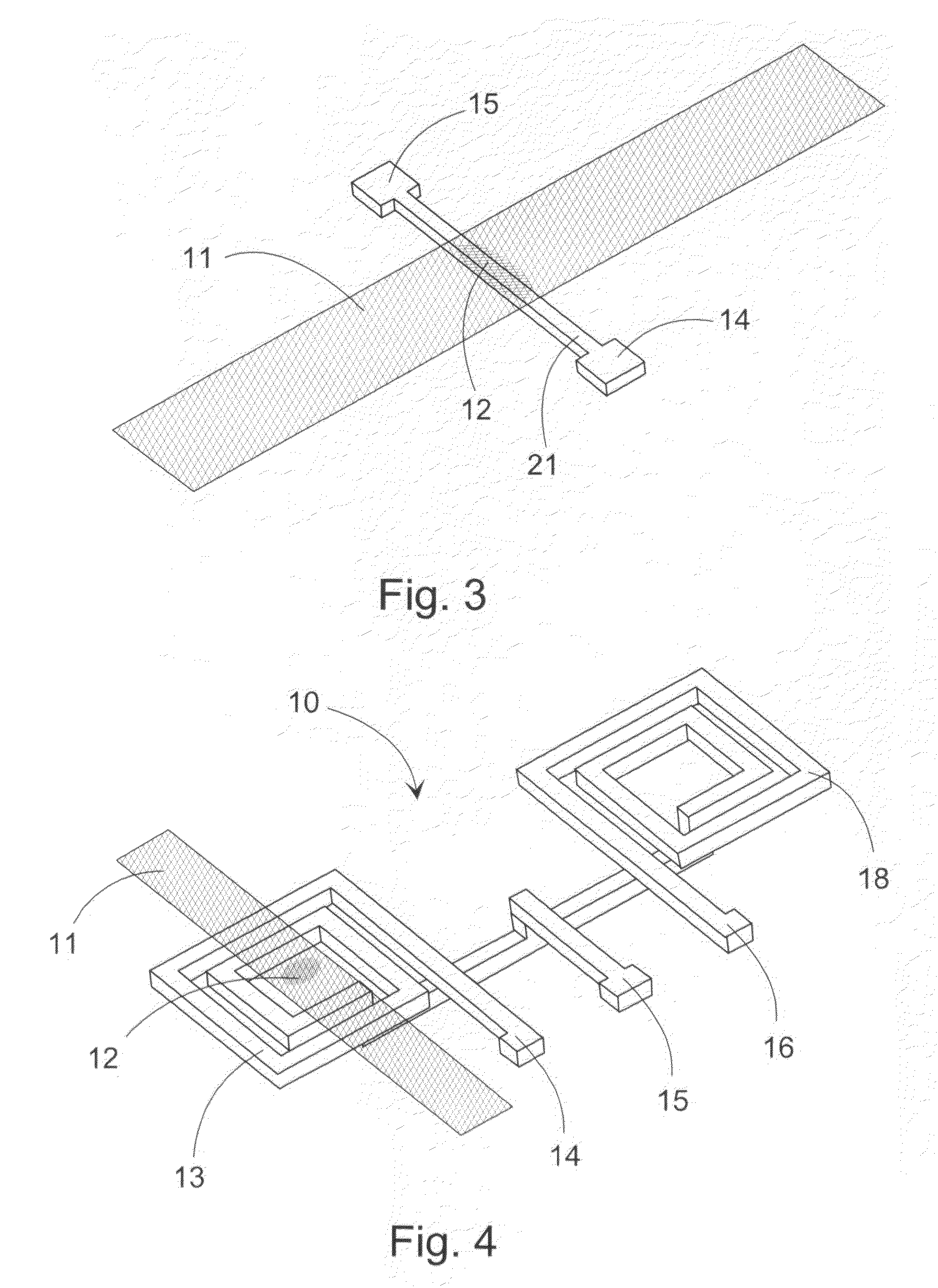
[0041]FIG. 5 shows a differential sensor-loop pair, which is now formed of two single-winding planar coil loops 13, 18 parallel to each other. The construction is slightly simpler than the embodiment shown in FIG. 4 and thus more affordable to manufacture. In this embodiment, the test base 11 with the magnetic particles 12 is placed transversely on top of both coils 13, 18. Having the test base 11 on top of both coils 13, 18 improves, among other things, the elimination of measurement errors caused by the test base 11. There is a connection to the measuring system from the contact terminals 14-16, of which 15 is again a common intermediate output for both coils 13, 18. It should be noted that each coil 13, 18 can also have its own contact terminal 14-16, independent of the embodiment.

[0042]In both embodiments, the measuring coil 13 and the reference coil 18 forming the compensating structure for that thus now form a differential coil arrangement. The reference coil 18 arranged in co...

third embodiment

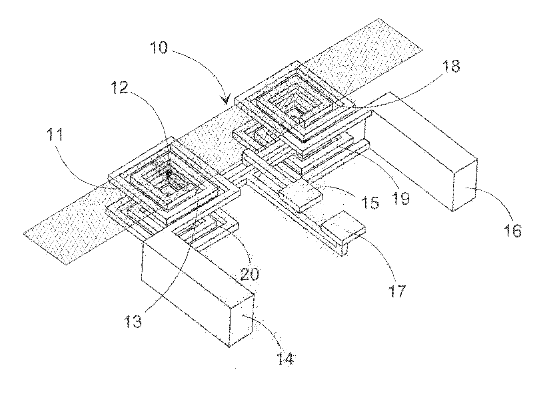
[0053]FIG. 10 shows bridge measurement, in which the coils 13, 18-20 are again on the same level, but in this base in a row formation. Again, the measuring coil 13 and the reference coil 18 are aligned symmetrically relative to the measuring-signal conductors 15, 17. Also in this case, the input-signal conductors 14, 16 come from the sides. The compensation coils 19, 20 are now at the ends of the coil array on either side of the measuring and reference coils 13, 18. The test base 11 with the magnetic particles 12 is again located transversely on top of all the coils 13, 18-20. One advantage of this construction is a better alignment relative to the test base 11.

[0054]According to yet another bridge-measurement embodiment, the coils 13, 18-20 can also be concentrically on a post. In this case, reference can be made to FIG. 9. The signal conductors of the measuring and reference coils 13, 18 can, differing from FIG. 9, also be run in such a way that if necessary insulating material ca...


PUM


Abstract

The invention concerns a device for the qualitative or quantitative measurement of a magnetically labelled analyte. The device includes a coil arrangement for measuring the analyte from a sample absorbed in a test base. The coil arrangement includes at least one measuring coil and a reference coil arranged in connection with it. From the signal of the coil arrangement a change in inductance correlating to the content of the magnetically labelled analyte is arranged to be detected. The change in inductance is arranged to be detected from a change (ΔA, Δφ) in amplitude and/or phase appearing in the output signal of the coil arrangement, which is arranged to be measured at the frequency of the input signal. In addition, the invention also relates to a corresponding method.

Description

BACKGROUND OF THE INVENTION[0001]The present invention concerns a device for the qualitative or quantitative measurement of a magnetically labelled analyte, which device includes a coil arrangement, formed of at least one measuring coil and a reference coil arranged in connection with it, for measuring the analyte from a sample absorbed in a test base, and from the signal of which coil arrangement a change in inductance correlating to the content of the magnetically labelled analyte is arranged to be detected. In addition, the invention also relates to a corresponding method.[0002]Numerous methods and apparatuses for measuring magnetic particles, for example, in analytic tests, are known from the prior art. For example, Finnish patent number 113297 discloses an idea concerning the use of a so-called astatic coil arrangement for measuring an analyte from a sample absorbed in a test base. In it, the coil arrangement is used to detect a change in inductance correlating to the content o...

Claims


Application Information

Patent Timeline
IPC IPC(8): G01B7/30
CPCB03C1/015G01R33/12G01R33/1269G01R33/1276G01N33/54326B03C2201/24B03C2201/26G01N2333/4737G01N35/0098G01N27/72G01N33/543
Inventor MAKIRANTA, JARKKOLEKKALA, JUKKA
Owner DIASYS DIAGNOSTIC SYST
Why Eureka
Try Eureka