Ink jet print head which prevents bubbles from collecting

a print head and jet print technology, applied in printing, inking apparatus, etc., can solve the problems of adversely affecting the response speed of the head, affecting the emission frequency of the head, and the actuator cannot be formed too close to the slot, so as to achieve the effect of greater probability of bubble formation and bubble formation

Active Publication Date: 2011-10-04
SICPA HLDG SA +1
View PDF12 Cites 3 Cited by
  • Summary
  • Abstract
  • Description
  • Claims
  • Application Information

AI Technical Summary

Benefits of technology

[0018]According to the present invention, the Applicant has observed that bubble formation is substantially limited when the distance between the ink supply slot and the ejection chambers is relatively short and the ink path is direct, while the probability of bubble formation is greater when the distance between the ink supply slot and the ejection chamber is longer.
[0019]In particular, the Applicant has observed that, where the distance between the ejection chambers and the feed slot is relatively short, particularly in the case of ejection chambers facing the edge of the slot itself, any small bubbles which are formed can be rapidly collected in the wide passage formed by the feed slot and can travel away from the emission area without causing problems, and that it is therefore useful to reduce the obstacles to the flow of ink in these areas.
[0022]In the case of ejection chambers located at the ends of the feed slots, preventive elements can efficiently prevent the formation and growth of bubbles without changing the hydraulic characteristics of the head, these elements being preferably configured in a suitable way.
[0023]According to the present invention, therefore, it has been found that the formation or growth of bubbles in an ink jet print head can be substantially limited without changing the hydraulic characteristics of the feed circuit of the emission chambers, by placing projecting elements next to the peripheral emission chambers of each fluid feed slot and substantially in alignment with the lateral edges of these emission chambers.
[0024]Thus, in the case of these marginal ejection chambers, the presence of obstacles to the ink flow was substantially limited, thereby avoiding the creation of areas of deceleration or stagnation of the said ink in which bubbles could collect and grow, while care was also taken to avoid leaving relatively large areas where possible small bubbles could grow.

Problems solved by technology

For reasons of cost, the distribution slots are commonly formed by machining processes, such as sandblasting, which are inherently relatively rough.
The actuators cannot be formed too close to the slots, because of the large tolerances on the sizes and profiles of the walls of the slots.
Flat surfaces such as the flat bases of these manifolds tend to collect and grow air bubbles which may impede or block the flow of fluid from the feed slots to the drop generators.
Furthermore, the presence of these projections in front of the passages leading the ink towards the ejection chambers disturbs the flow of the ink, thus adversely affecting the response speed of the head.
The Applicant has observed that the prior art solutions have elements for preventing bubble formation which affect the path of the fluid towards the ejection chambers in an irregular way, thus changing the hydraulic impedance which determines the capacity of the said chambers to be fed with new fluid after each emission, and consequently affecting the emission frequency of the head.

Method used


Image

  • Ink jet print head which prevents bubbles from collecting
  • Ink jet print head which prevents bubbles from collecting
  • Ink jet print head which prevents bubbles from collecting

Examples


Embodiment Construction

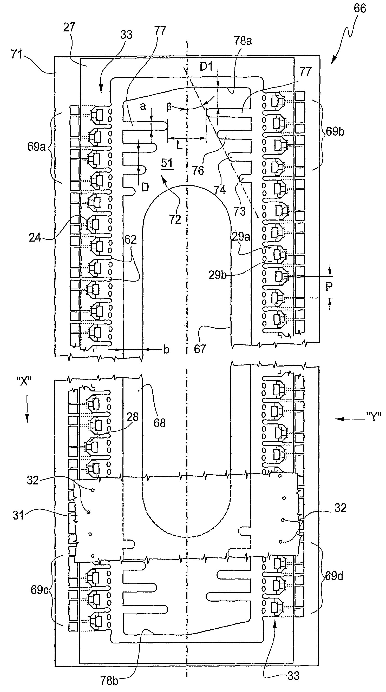
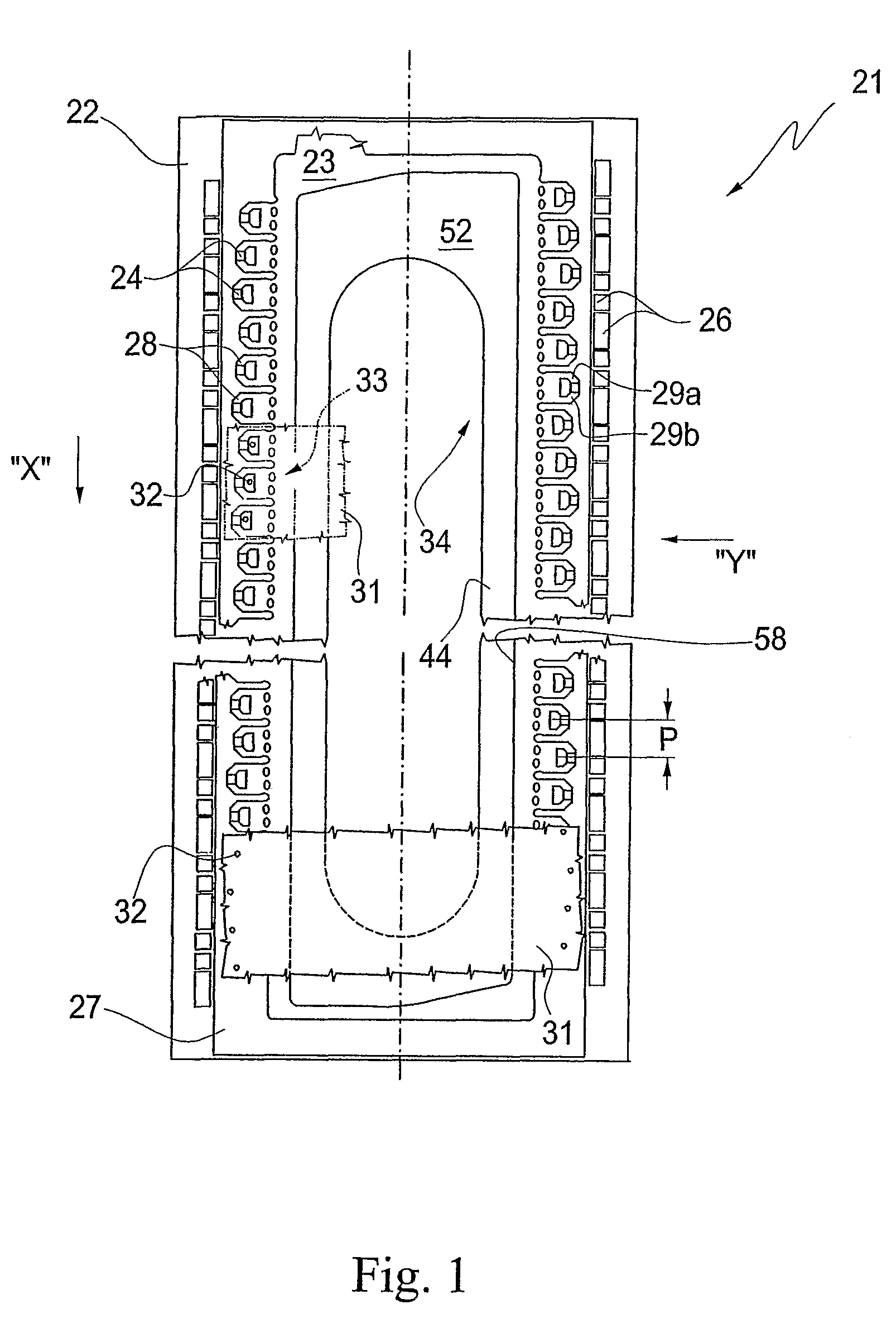
[0058]FIG. 1 shows schematically part of a thermal ink jet print head 21 with “top shooter” actuators, comprising a substrate plate 22 of rectangular shape, elongated in the longitudinal direction and having an upper surface 23.

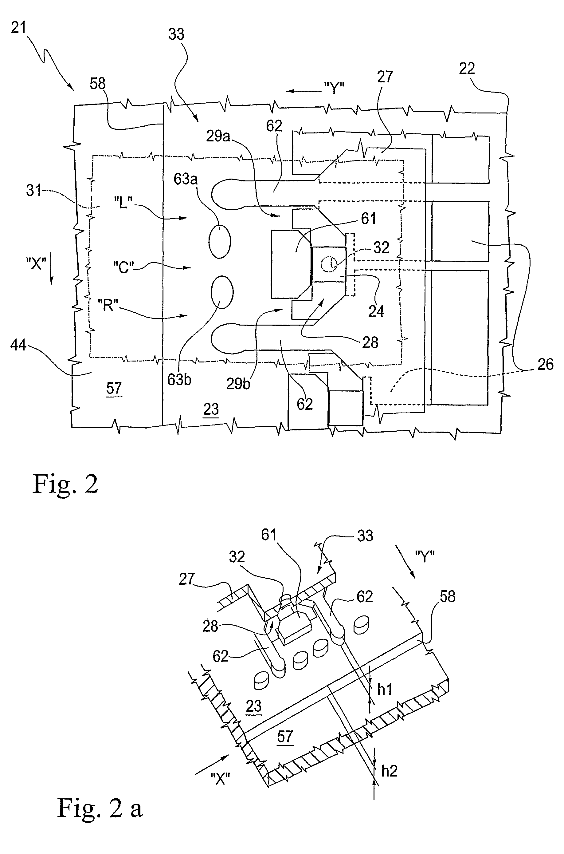
[0059]The substrate plate 22 is usually made from silicon, although other materials can be used. Layers of thin film which form a plurality of emission resistors 24 and conductors 26, and a structural layer 27, are placed on the surface 23.

[0060]The layer 27 forms the walls of ejection chamber 28 and of supply passages 29a and 29b. It is made from photopolymer, for example, and has a thickness “h1” of 15-30 μm.

[0061]For the purposes of the present description, the term “photopolymer” denotes a material whose polymerization is activated or controlled by light radiation, for example by UV radiation.

[0062]An orifice plate 31, made for example from metal or plastics material, in which ejection orifices 32 are formed to correspond to the chambers 28, is bonded in ...


PUM


Abstract

Ink jet print head comprising a substrate with an upper surface and a lower surface; a plurality of actuators with ejection chambers and ink supply passages, an ink distribution slot formed in the substrate between the lower surface and the upper surface; a manifold formed in the substrate of the upper surface around the slot for the feed to the actuators; and a plurality of bubble prevention elements formed in the feed manifold. The plurality of bubble prevention elements is provided only for a marginal set of actuators remote from the distribution slot.

Description

TECHNICAL FIELD[0001]The invention relates to ink jet print heads, and more particularly to ink jet print heads of the thermal type and the method for their manufacture.BRIEF DESCRIPTION OF THE PRIOR ART[0002]For ink jet printing, use is made of print elements, each of which typically comprises an ink tank and a print head connected to it.[0003]In its turn, the print head, particularly in the case of what is known as a thermal head, comprises a plurality of actuators, positioned in one or more rows, each provided with an ejection chamber and a corresponding emission nozzle. The construction and mode of operation of ink jet print heads, particularly those of the thermal “top shooter” type, in other words those having actuators which emit ink drops in a direction perpendicular to an ejection chamber, are known in the art and consequently will not be described here in detail.[0004]In serial printers, the head is moved transversely with respect to the surface to be printed, and the leng...

Claims


Application Information

Patent Timeline
Patent Type & Authority Patents(United States)
IPC IPC(8): B41J2/19B41J2/05
CPCB41J2/1404B41J2/14145B41J2002/14387B41J2002/14403B41J2002/14467B41J2202/07
Inventor SASSANO, DUCCIO SPARTACOSCARDOVI, ALESSANDROMARTINA, GIANCARLO
Owner SICPA HLDG SA
Why Eureka
Try Eureka