Device and method for detecting back electromotive force phase and device and method for controlling excitation

a technology of back electromotive force and excitation control, which is applied in the direction of electric programme control, dynamo-electric converter control, instruments, etc., can solve the problems of increasing the number of parts, increasing the number of factors for failure, and increasing the cost, so as to prevent the motor from falling out

Active Publication Date: 2011-10-04
GK BRIDGE 1
View PDF6 Cites 2 Cited by
  • Summary
  • Abstract
  • Description
  • Claims
  • Application Information

AI Technical Summary

Benefits of technology

[0004]However, if the detector is attached to the motor, not only cost increases, but also the number of parts increases, i.e., the number of factors for failure increases. In view of this problem, an object of the present invention is to detect a back electromotive force phase without providing a detector for a two-phase excitation stepper motor that is driven with constant-current PWM. Another object of the present invention is to provide an excitation control that can prevent the stepper motor from falling out of synchronization, based on the result of such detection of a back electromotive force phase.
[0006]A second aspect of the present invention is directed to an excitation control device or method for controlling a motor drive device for driving a stepper motor by two-phase excitation with constant-current PWM. The device or method includes a control pulse generating unit for or step of supplying a control pulse indicating a rotation angle of the stepper motor to the motor drive device, a reference voltage generating unit for or step of supplying to the motor drive device a reference voltage that is a reference for the constant-current, and a control unit for instructing the reference voltage generating unit to change the reference voltage or a step of changing the reference voltage, based on an output of the back electromotive force phase detecting device or a result of the detection by the back electromotive force phase detecting method. Thereby, it is possible to prevent the motor from falling out of synchronization by changing the capability of driving the motor based on the detected back electromotive force phase.

Problems solved by technology

However, if the detector is attached to the motor, not only cost increases, but also the number of parts increases, i.e., the number of factors for failure increases.

Method used


Image

  • Device and method for detecting back electromotive force phase and device and method for controlling excitation
  • Device and method for detecting back electromotive force phase and device and method for controlling excitation
  • Device and method for detecting back electromotive force phase and device and method for controlling excitation

Examples


first embodiment

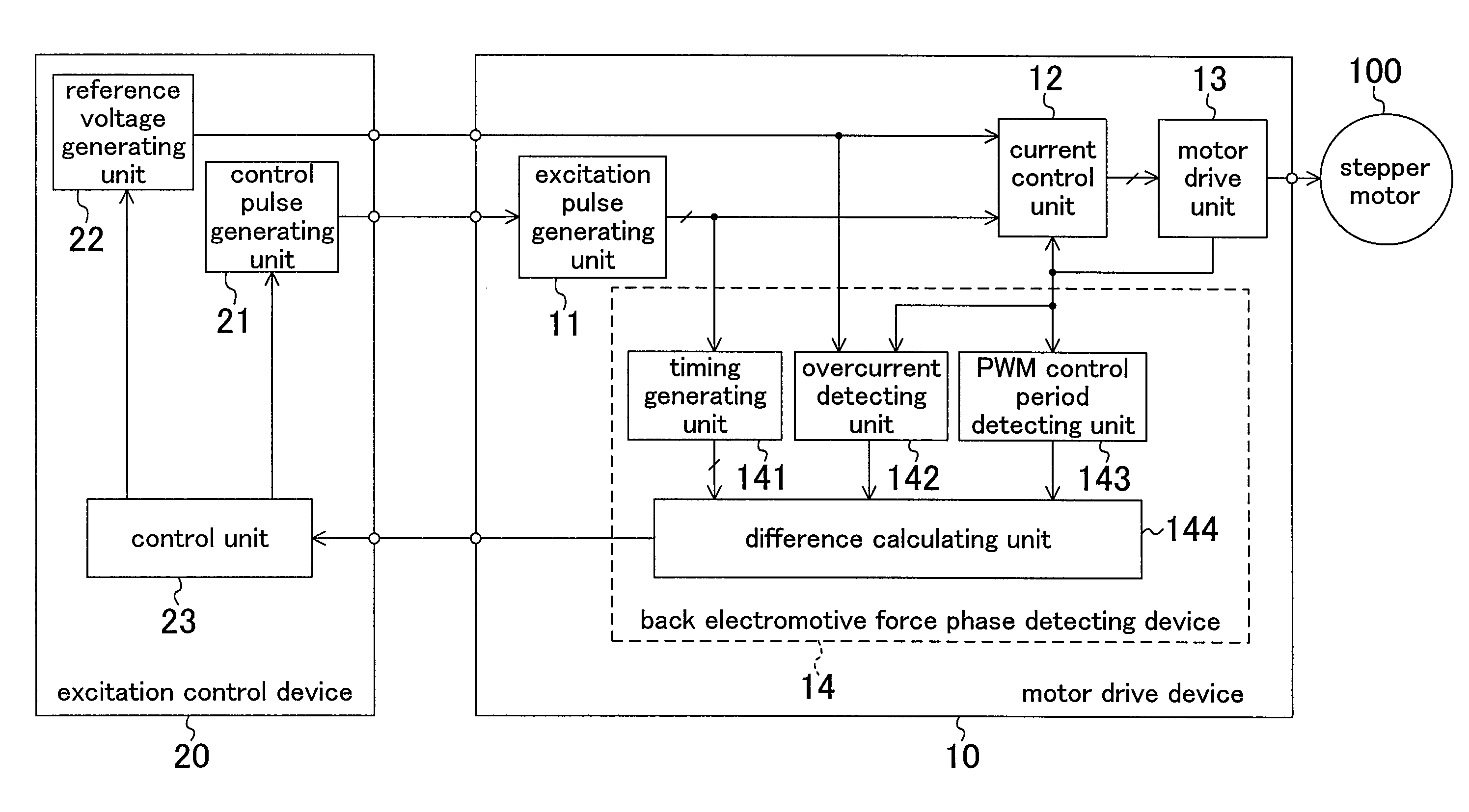
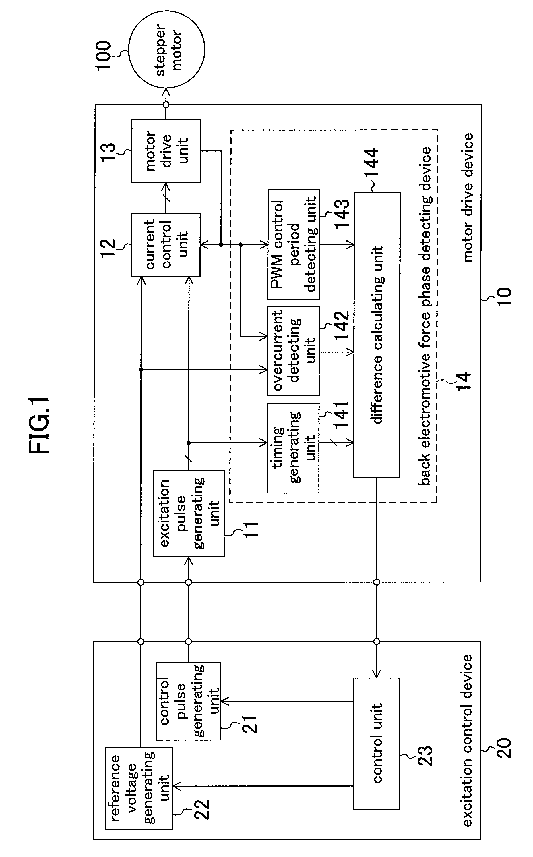
[0017]FIG. 1 shows a configuration of a system for driving a two-phase excitation stepper motor according to a first embodiment. In a motor drive device 10, an excitation pulse generating unit 11 generates an excitation pulse signal for adjusting and determining timing with which each motor coil of a motor 100 is excited based on supplied control pulses. A current control unit 12 generates an excitation control signal for performing constant-current PWM drive with respect to the motor 100, based on a supplied excitation pulse signal, a reference voltage, and a shunt resistance voltage. The motor drive unit 13 performs constant-current PWM drive with respect to the motor 100 by means of two-phase excitation in accordance with a supplied excitation control signal.

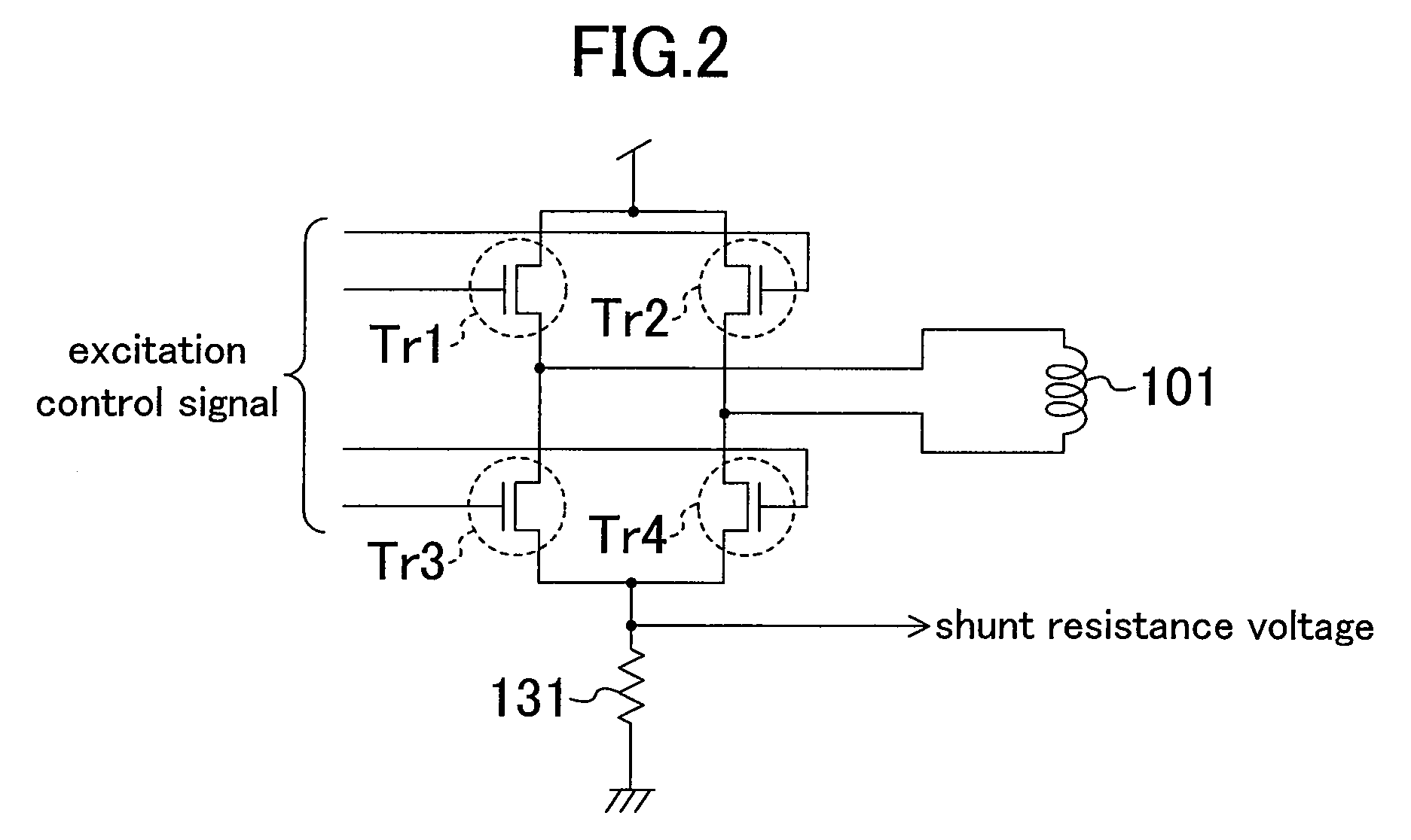
[0018]FIG. 2 shows an internal configuration of the motor drive unit 13. Four transistors Tr1, Tr2, Tr3 and Tr4 constitute an H bridge. By switching and controlling these transistors, a magnitude and a direction of a drive cu...

second embodiment

[0040]FIG. 9 shows a configuration of a two-phase excitation stepper motor drive system according to a second embodiment. The second embodiment is different from the first embodiment in the following points. Specifically, in the back electromotive force phase detecting device 14, the difference calculating unit 144 receives an excitation control signal that is output as a signal indicating a PWM ON or OFF period from the current control unit 12. As shown in FIG. 3, the excitation control signals of the four transistors include signals indicating a PWM ON or OFF period, and therefore, the difference calculating unit 144 can obtain the PWM ON or OFF period from the excitation control signals. According to this embodiment, the PWM control period detecting unit 143 is not required, so that the circuit scale can be reduced.

[0041]Note that, the overcurrent detecting unit 142 can be removed in both the first and second embodiments. A PWM ON period when an overcurrent occurs is considerably...


PUM


Abstract

In a back electromotive force phase detecting device, a timing generating unit generates a timing signal indicating a start timing, an intermediate timing and an end timing of a 180-degree electrical angle period in a detection target phase, from an excitation pulse signal. A difference calculating unit receives the timing signal, and calculates a difference between a total PWM control period of the detection target phase during a first-half 90-degree period, and a total PWM control period of the detection target phase during a second-half 90-degree period. In an excitation control device, a control unit changes the capability of driving a motor based on an output of the back electromotive force phase detecting device.

Description

BACKGROUND OF THE INVENTION[0001]The present disclosure relates to back electromotive force phase detection and excitation control for a stepper motor. More particularly, the present invention relates to back electromotive force phase detection and excitation control for a two-phase excitation stepper motor that is operated by constant-current PWM drive.[0002]Stepper motors are generally driven by an open-loop control. Therefore, if a drive current is insufficient (i.e., drive torque is insufficient), then the stepper motor immediately falls out of synchronization. Therefore, an excessive amount of drive current is supplied to the stepper motor so as to secure a sufficient drive torque margin to overcome any load torque.[0003]In order to reduce the power consumption of the stepper motor, it is necessary to detect a sign that the stepper motor will fall out of synchronization during an increase in load torque that occurs suddenly, and increase a drive current as required. Conventiona...

Claims


Application Information

Patent Timeline
Patent Type & Authority Patents(United States)
IPC IPC(8): G05B19/40H02P8/38
CPCH02P6/182
Inventor ITO, DAISUKEMORI, HIDEAKIYAMAMOTO, YASUNORI
Owner GK BRIDGE 1
Why Eureka
Try Eureka