
Low-pass filter

a filter and low-pass technology, applied in the field of low-pass filter, can solve the problems of increasing the packaging cost of the controller chip, occupying considerable layout space, and still failing to meet the low bandwidth requirement of power supplies, and achieve the effect of reducing the prime cos

Active Publication Date: 2011-10-04
SEMICON COMPONENTS IND LLC
View PDF4 Cites 3 Cited by
  • Summary
  • Abstract
  • Description
  • Claims
  • Application Information

AI Technical Summary

Benefits of technology

The solution enables efficient low-pass filtering with reduced packaging costs and layout space, while maintaining the same filtering performance as external bulk capacitors, thus addressing the limitations of conventional designs.

Problems solved by technology

Thus, extra pins must be added to the controller chip for coupling to the external compensation capacitors, which increases the packaging cost of the controller chip.
Furthermore, since the external compensation capacitors are usually bulk capacitors, they will occupy considerable layout space if they are integrated within the controller chip.
Nowadays, although various types of low-pass filters are able to integrate within the controller chip, they still failed to meet low bandwidth requirement of power supplies.
This is because most of their bandwidths are too high due to the consideration of saving layout space.
That is, the bandwidth of the low-pass filter is not low enough, and therefore the medium-high frequency harmonic of the input signal SIN cannot be filtered efficiently.
The integrated layout space of the second capacitor 76 will therefore inevitably increase, which also increases the integration cost of the controller chip.

Method used


Image

  • Low-pass filter
  • Low-pass filter
  • Low-pass filter

Examples


Embodiment Construction

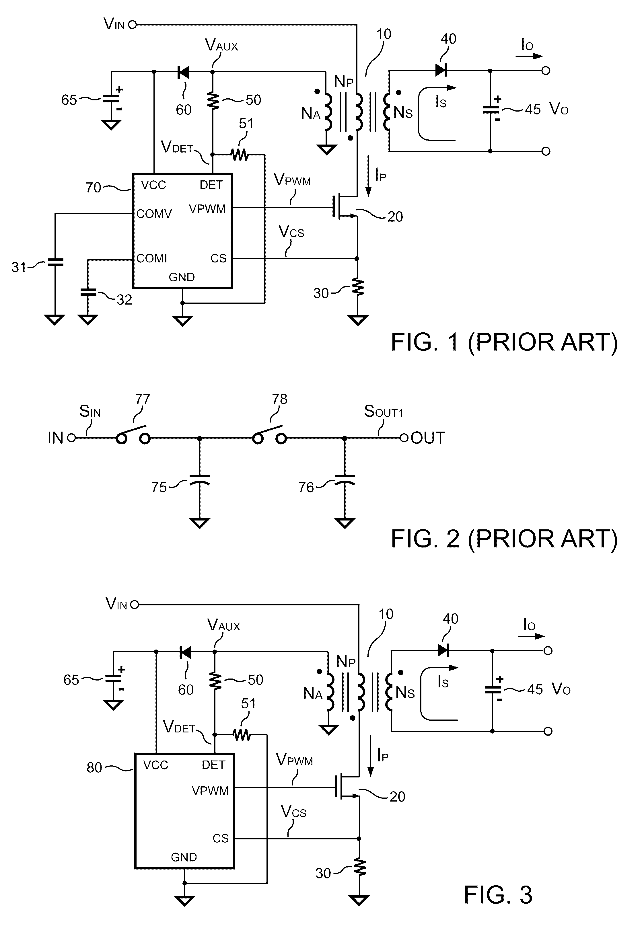
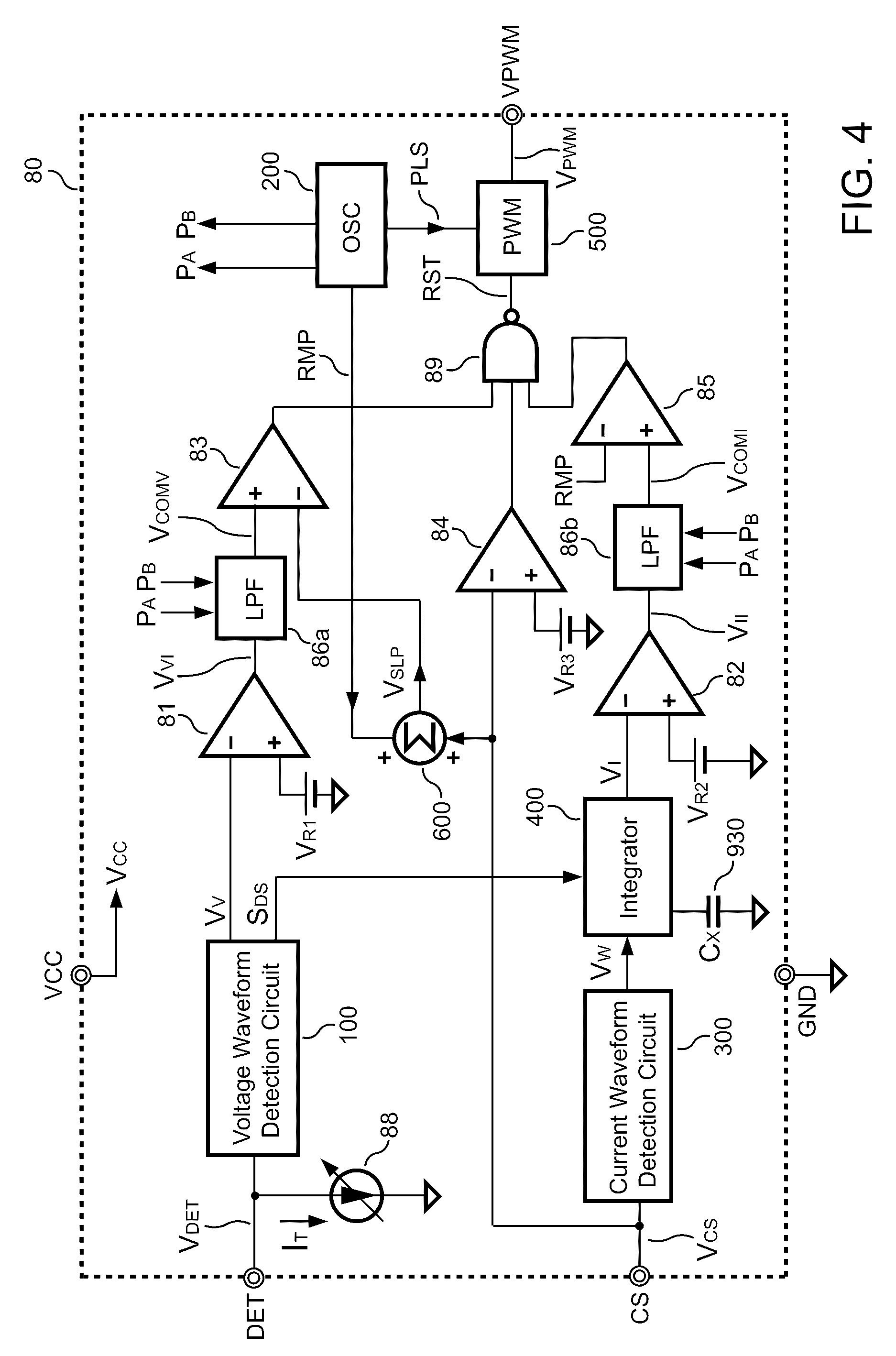
[0027]FIG. 3 shows a circuit diagram of an embodiment of the power supply according to the present invention. The power supply includes a transformer 10 having a primary winding NP, a secondary winding NS, and an auxiliary winding NA. The primary winding NP is coupled to the input voltage VIN and connected to a transistor 20 and a resistor 30 in series. The resistor 30 is coupled to a ground reference. A controller 80 includes a power supply terminal VCC, a ground terminal GND, a detection terminal DET, a sense terminal CS, and a PWM (pulse width modulation) terminal VPWM. The PWM terminal VPWM of the controller 80 generates a switching signal VPWM to control the transistor 20 for switching the transformer 10 and regulating an output voltage VO and / or an output current IO of the power supply.

[0028]A terminal of the secondary winding NS is coupled to a rectifier 40. A filter capacitor 45 is coupled between the rectifier 40 and another terminal of the secondary winding NS. When the tr...


PUM


Abstract

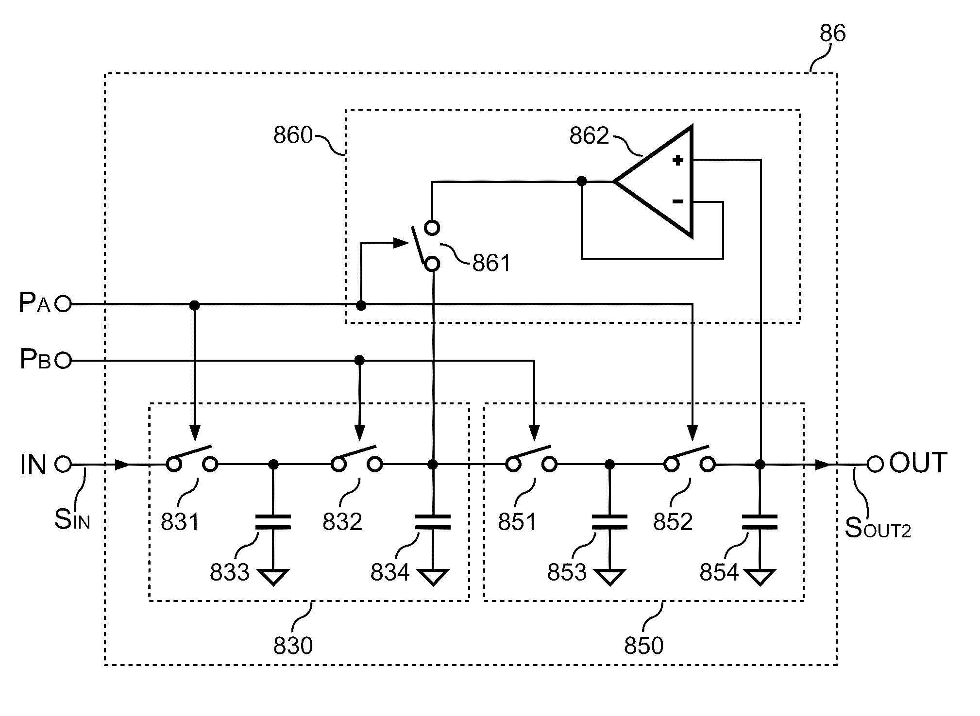
A low-pass filter of the present invention comprises a plurality of filter units and a regulation unit. The filter units are coupled in series with each other and receive an input signal to filter the input signal for generating an output signal. The regulation unit is coupled to the filter units to regulate voltage levels of the filter units. The low-pass filter of the present invention can be integrated within the integrated circuit and reduce the prime cost.

Description

BACKGROUND OF THE INVENTION[0001]1. Field of the Invention[0002]The present invention relates to a low-pass filter, and more particularly to a low pass-filter capable of being integrated in the integrated circuit and reduce the prime cost.[0003]2. Description of the Prior Art[0004]Power supplies are widely applied to provide regulated voltage and current for various electronic products. To improve the stability of the power supplies, compensation capacitors are usually coupled to the control integrated circuit (controller chip) of the power supplies externally. Thus, extra pins must be added to the controller chip for coupling to the external compensation capacitors, which increases the packaging cost of the controller chip. Furthermore, since the external compensation capacitors are usually bulk capacitors, they will occupy considerable layout space if they are integrated within the controller chip. Detailed explanation is given below to describe disadvantages of the above. Referri...

Claims


Application Information

Patent Timeline
Patent Type & Authority Patents(United States)
IPC IPC(8): H03K5/00
CPCH02M3/156H03H11/1291
Inventor LU, RUI-HONGHSU, SHENG-FU
Owner SEMICON COMPONENTS IND LLC
Learn More