
Optical sheet retaining tool and chassis for liquid crystal display device

a technology of liquid crystal display device and retaining tool, which is applied in the manufacture of electrode systems, electric discharge tubes/lamps, instruments, etc., can solve the problems of large amount of material, inability to reduce display apparatus costs, and waste of scrap materials, so as to reduce material costs, material costs, and the effect of reducing the cost of scrap material

Inactive Publication Date: 2011-10-04
TAISEI PLAS CO LTD
View PDF19 Cites 31 Cited by
  • Summary
  • Abstract
  • Description
  • Claims
  • Application Information

AI Technical Summary

Benefits of technology

The present invention provides an optical sheet retaining tool for a liquid crystal display device that is simple and low-cost, and easy to assemble and disassemble. The tool includes a first retaining piece and a second retaining piece made of soft material for gripping and retaining the optical sheet. The tool also has a latching section for gripping and fixing the first and second retaining parts under a state in which the optical sheet is gripped between them. The tool is made up of a bearing section that serves as a bearing for gripping the optical sheet. The invention also provides a chassis for the display device that includes the optical sheet retaining tool, which is easy to assemble and disassemble. The technical effects of the invention are improved retention of the optical sheet and simplified assembly and disassembly of the display device.

Problems solved by technology

Further, operations for fixing and retaining such optical sheets, as well as for removing the optical sheets for carrying out repairs and the like, have involved different complex operations for each type of machine.
However, when a large-scale screen chassis is used, a large sized sheet metal material must be used as well, and a core that is made by punching the central region of the sheet metal material is also rendered large in size in proportion thereto.
However, the creation itself of such large scale scrap material is problematic in terms of material costs, and further, there are problems in that costs must be expended on the handling and processing of such scrap material.
With such a structure, the costs for the display apparatus cannot be reduced, and further, upon assembling and disassembling the apparatus, the content of the work operations differ for each machine type, and thus are complicated.
Further, in the case of manufacturing the chassis of a large scale flat panel display device as in the prior art, by a sheet metal punching process or a press formation process, there are problems of costs associated with the handling and processing of scrap materials, and thus there have been problems in that manufacturing costs cannot be reduced.
Moreover, even with the chassis disclosed in Patent Document 2, in which square-shaped steel tubes are connected, the connecting process cannot be applied to mass production, and thus problems have resulted in that manufacturing costs cannot be reduced.

Method used


Image

  • Optical sheet retaining tool and chassis for liquid crystal display device
  • Optical sheet retaining tool and chassis for liquid crystal display device
  • Optical sheet retaining tool and chassis for liquid crystal display device

Examples


Embodiment Construction

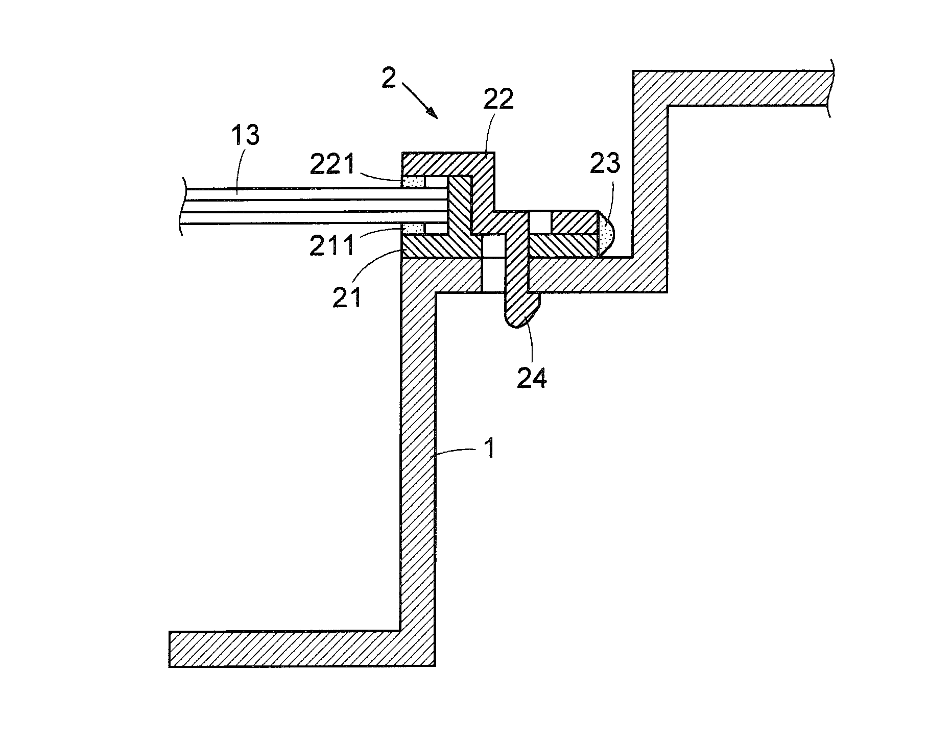
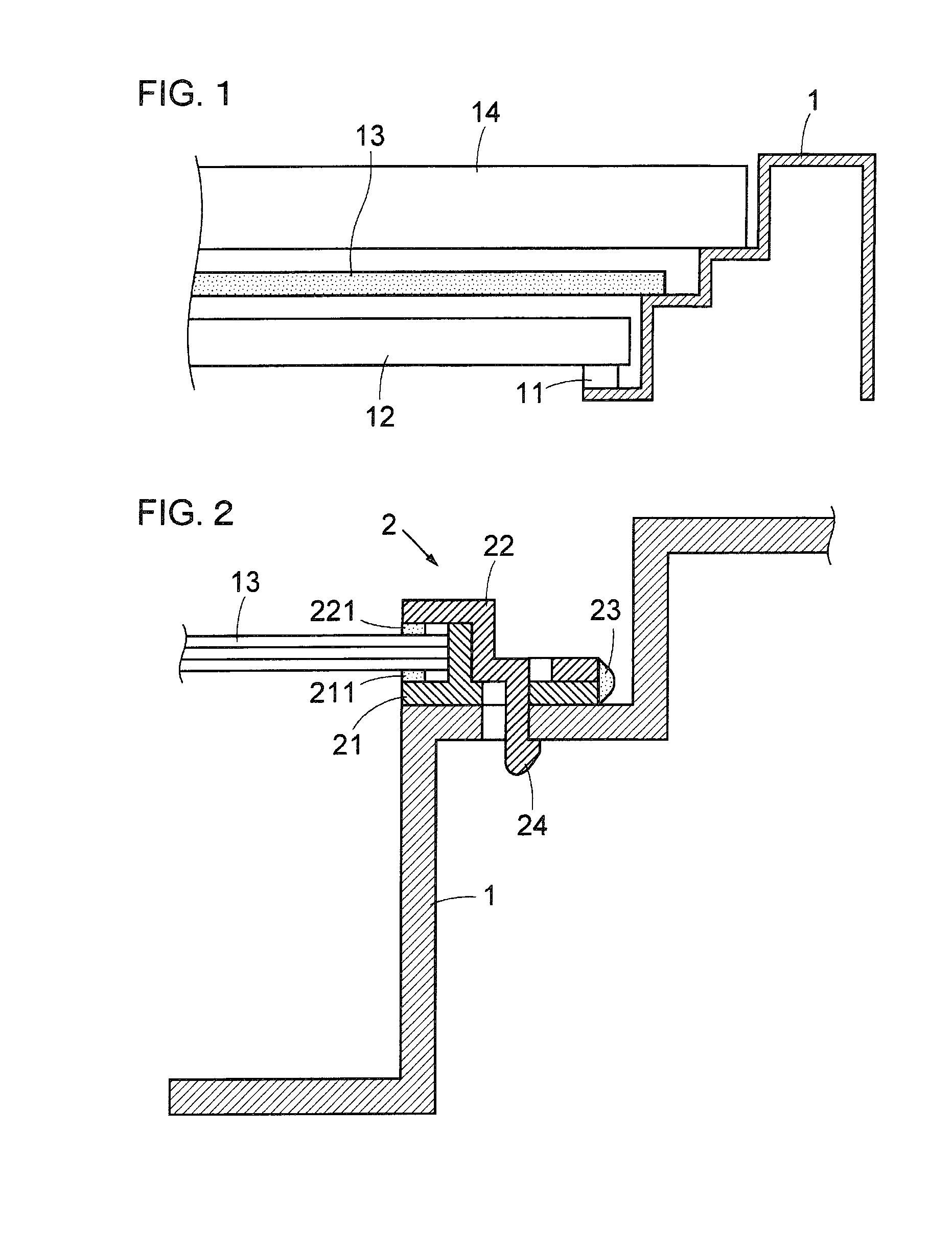
[0088]An embodiment of the present invention will be described below with reference to the figures. FIG. 1 is a view showing an anchored state of a chassis 1 of a liquid crystal display device. FIG. 1 shows a cross sectional view cut across a plane perpendicular to the display screen. A backlight 12 made up of fluorescent tubes is arranged on the back surface side as observed from the display screen of the chassis 1. The backlight 12 is supported by supporting members 11 affixed to the chassis 1.

[0089]An optical sheet 13 for uniformly diffusing and polarizing light from the backlight 12 is arranged more closely to the display surface side than the backlight 12. The optical sheet 13 is made up from a diffusion sheet, a prism sheet, a polarizing sheet or the like. The fixing structure by which the optical sheet 13 is affixed to the chassis 1 shall be explained in greater detail later. In addition, a liquid crystal display panel 14 serving as a display screen is arranged on a surface s...


PUM

PropertyMeasurementUnit
diameteraaaaaaaaaa
angleaaaaaaaaaa
inner diameteraaaaaaaaaa

Abstract

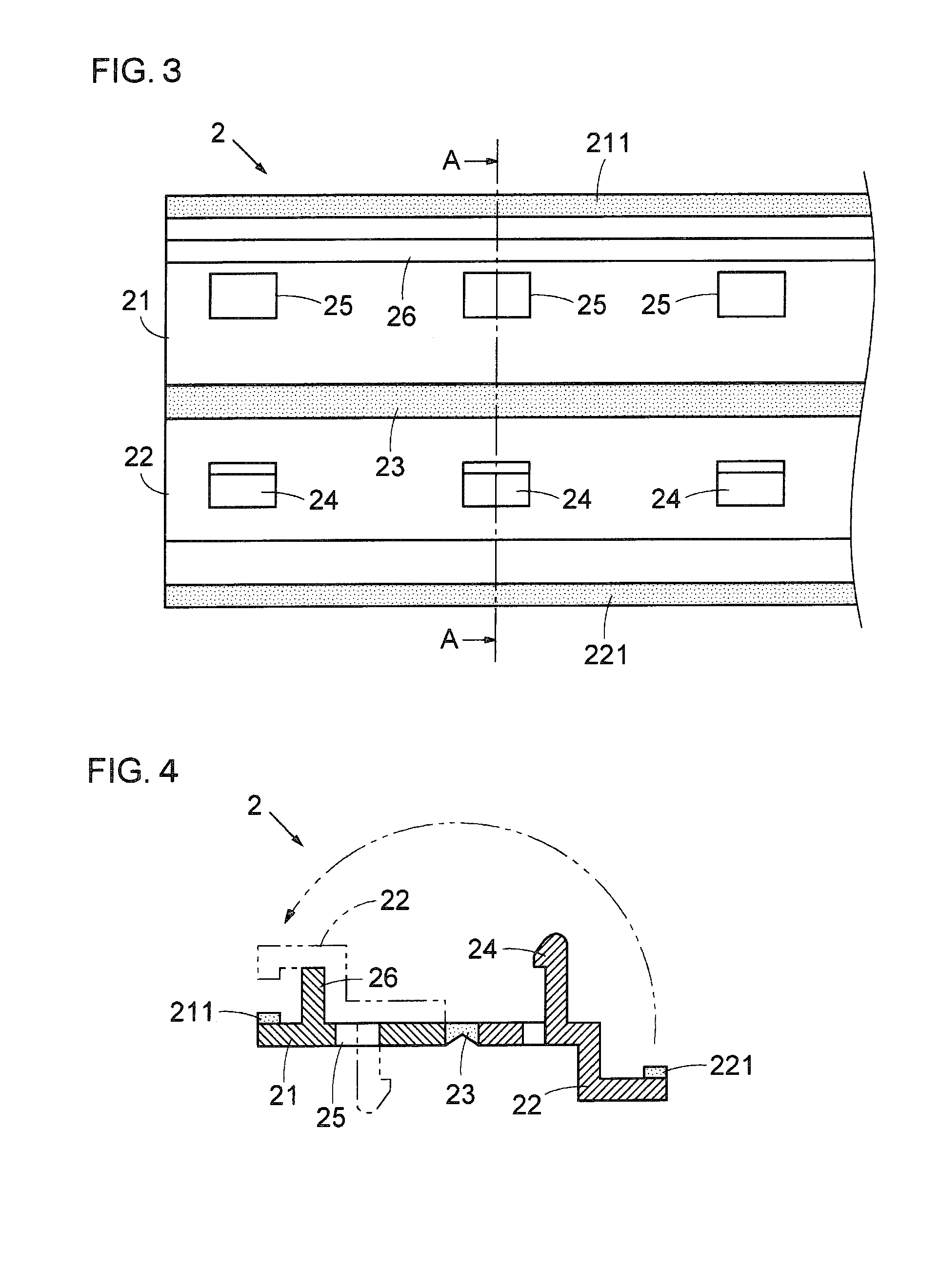
An optical sheet retaining tool for a liquid crystal display device that has a simple structure and low cost, wherein assembling and disassembling can be performed easily. The optical sheet retaining tool includes a first retaining piece 21 having a first retaining part 211 made of a soft material for retaining an optical sheet 13, a second retaining piece 22 having a second retaining part 221 made of a soft material opposed to and cooperating with the first retaining part for gripping and retaining the optical sheet, a latching section 24 for latching the first and second retaining parts with the optical sheet gripped therebetween, a fixing section 24 for retaining and fixing the first and second retaining pieces to a chassis 1, and a bearing section 23 disposed on at least one of the first and second retaining pieces for gripping the optical sheet.

Description

TECHNICAL FIELD[0001]The present invention relates to a retaining tool for fixing and retaining an optical sheet on a chassis, which is used in a backlit type of liquid crystal display device for a large-scale liquid crystal television apparatus or the like. More specifically, the invention concerns an optical sheet retaining tool for a liquid crystal display device, which is simple in structure, while enabling assembly and disassembly of the display device to be performed with ease.BACKGROUND ART[0002]Optical sheets, such as light diffusion sheets, prism sheets, polarizing sheets or the like, are used in backlit type liquid crystal display devices for large-scale liquid crystal television apparatus and the like. However, until the present time, for fixing and retaining these types of optical sheets on a chassis of the display device, individualized fixing structures have been designed and manufactured respectively for each type of display device. Further, operations for fixing and ...

Claims


Application Information

Patent Timeline
Patent Type & Authority Patents(United States)
IPC IPC(8): G02F1/1333G02F1/13357
CPCG02F1/133608G02F1/133606G02F2201/465G02F2201/54G02F1/1335
Inventor NARITOMI, MASANORI
Owner TAISEI PLAS CO LTD
Learn More