
Rolling bearing with improved rim geometry

Inactive Publication Date: 2011-10-11
SCHAEFFLER TECH AG & CO KG
View PDF13 Cites 7 Cited by
  • Summary
  • Abstract
  • Description
  • Claims
  • Application Information

AI Technical Summary

Benefits of technology

[0013]Preferably the aperture angle between the raceway and the rim bearing surface is greater than 90°. In the case of evenly curved surfaces, in order to determine the rim aperture angle, a straight line is considered, said line running in the radial direction of the rolling bearing through the starting point and the end point of the curvature. As a result of this embodiment, instead of a contact area between the front face of the rolling bearing and the rim bearing surface, there is a contact point with a gap gradually opening outwards. In this way a frictionally favorable contact is established, resulting in favorable penetration of lubricant and thus a smaller amount of friction.
[0014]In addition, as a result of the inventive constructional form of the rim bearing surface and the front face of the rolling body, an effectively round geometry is obtained in the region of contact and thus a high tolerance with respect to tilting or skewing of the roller is achieved.
[0016]Preferably both the front face and the rim bearing surface are curved in a convex manner in the direction of the respective other surface or face. In this way particularly favorable penetration of lubricant may be achieved. It is also possible, however, for one of the two surfaces to be curved in a concave manner, in which case the corresponding convex radius of curvature is particularly preferably smaller than the concave radius of curvature.
[0018]Preferably at least one component of the rolling bearing according to the invention is produced by means of a hard turning process. By using the hard turning process it is possible to achieve low-cost production of the torus radii mentioned.

Problems solved by technology

The result of such edge loading is a reduced working life of the rolling bearing.
Thus the contact surface of these rolling bodies is at least on the rim shoulder to a certain degree truncated, resulting in a limited axial load capacity during rim contact.

Method used


Image

  • Rolling bearing with improved rim geometry
  • Rolling bearing with improved rim geometry

Examples


Embodiment Construction

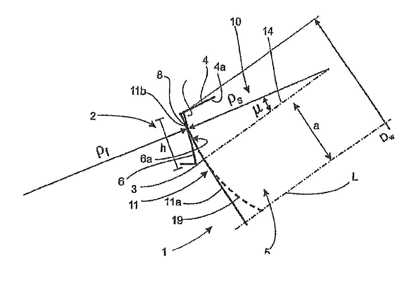
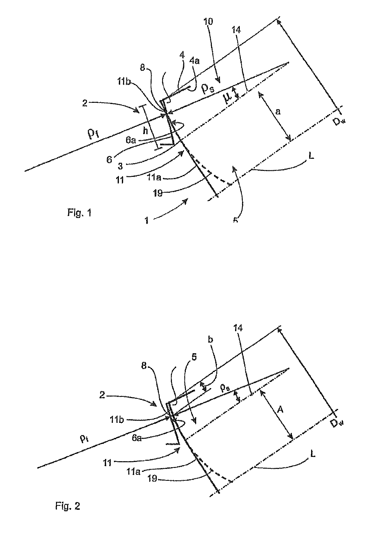
[0029]FIG. 1 shows a schematic sectional representation of a rolling bearing 1 according to the invention, illustrating the geometrical layout thereof. In this connection the reference number 5 refers to a rolling body for a tapered roller bearing, although only a part of the front face 11 of this rolling body is shown.

[0030]This front face 11 of the rolling body 5 has a central section 11a as well as an edge region 11b. In this embodiment the central section 11a extends substantially in the form of a straight line and the edge region 11b is curved. The reference number 6 refers to a lateral rim of a bearing ring 2 which has a rim bearing surface 6a which faces the front face 11 of the rolling body 5.

[0031]In the embodiment shown in FIG. 1 the central section 11a of the front face 11 does not make contact against the rim bearing surface 6a of the rim 6. Therefore the central region 11a of the front face 11, instead of extending in the form of a straight line, may also extend in subs...


PUM


Abstract

A rolling bearing which has at least one bearing ring and a plurality of rollers. The bearing ring has a raceway for the rollers and at least one lateral rim for axially guiding the rollers. The roller has front face facing the rim and the rim has a rim hearing surface facing the roller. At least sections of at least the front face or the rim bearing surface have a toroidal camber in the direction of the rim bearing surface or the front face.

Description

FIELD OF THE INVENTION[0001]The invention relates to a rolling bearing. The present invention is described with reference to tapered roller bearings, although it is pointed out that the invention may also be applied to other types of bearing, such as cylindrical roller bearings or self-aligning ball bearings.BACKGROUND OF THE INVENTION[0002]According to the state of the art, roller bearings are known which, with reference to a raceway, have lateral rims for absorbing axial stress components. In this connection, according to the state of the art, cylindrical roller bearings with flat roller front faces and flat rim faces are known. These bearings give rise to edge loading of the rolling body with respect to the rim. The result of such edge loading is a reduced working life of the rolling bearing.[0003]In addition, according to the state of the art, cylindrical roller bearings are known where the front face of the rolling bodies is formed in the manner of a spherical cap. In the case ...

Claims


Application Information

Patent Timeline
IPC IPC(8): F16C33/58F16C19/00
CPCF16C19/225F16C19/364F16C33/34F16C2240/40F16C33/366F16C2360/31
Inventor DE MUL, JAN
Owner SCHAEFFLER TECH AG & CO KG
Learn More