
Charge coupled pump-efficient charge pump regulator with MOS capacitor

a charge pump and capacitor technology, applied in the field of charge pumps, can solve the problems of inability to step up or invert input voltage, charge pump efficiency degradation, and inefficient and achieve the effect of efficient operation of charge pump regulators

Active Publication Date: 2011-10-18
WESTERN DIGITAL ISRAEL LTD
View PDF19 Cites 82 Cited by
  • Summary
  • Abstract
  • Description
  • Claims
  • Application Information

AI Technical Summary

Benefits of technology

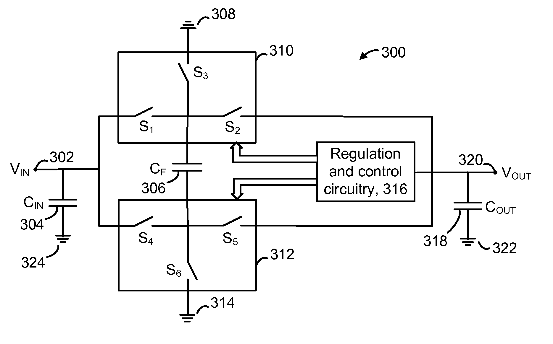
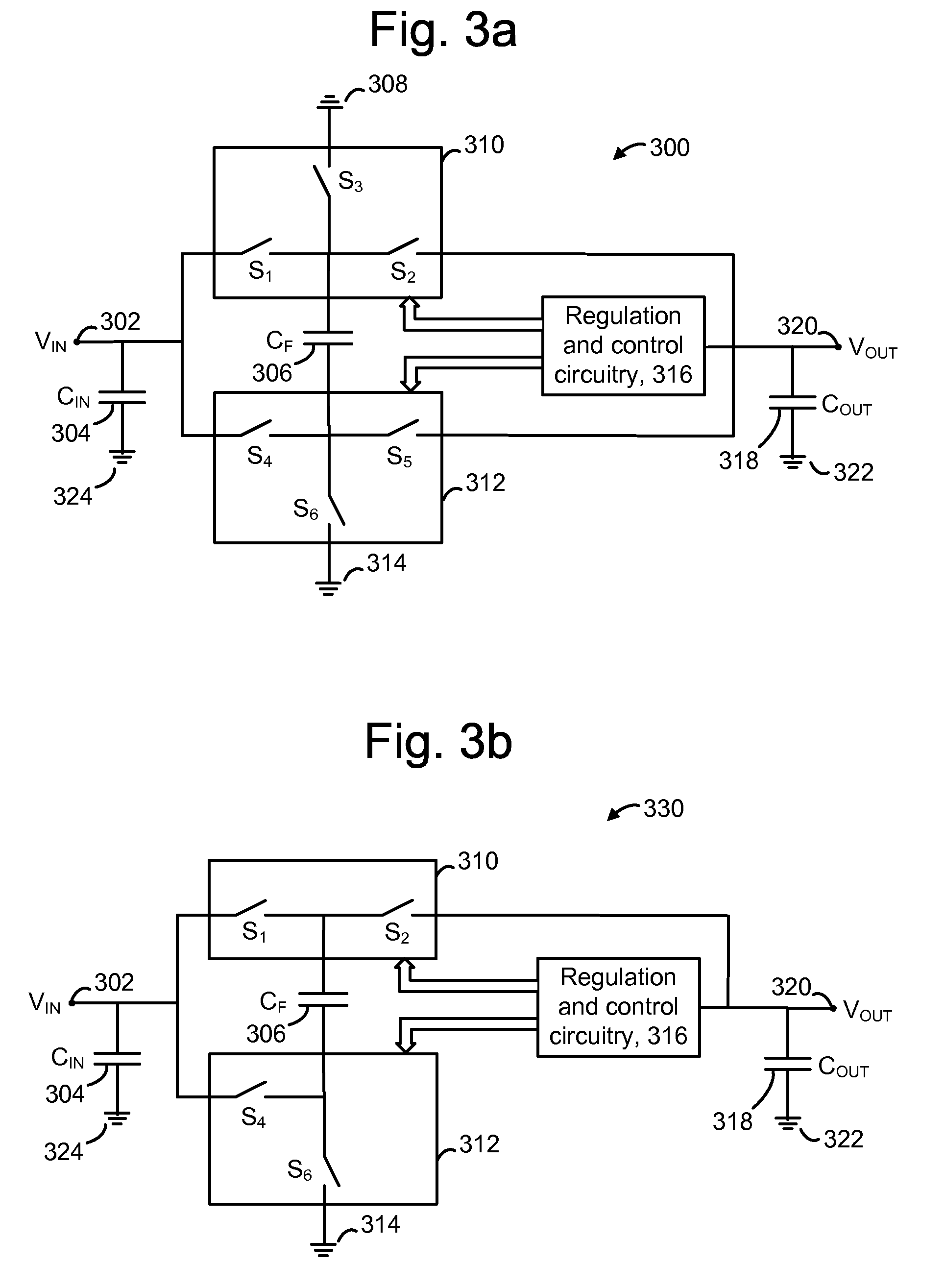
"The present invention provides a method for efficiently operating a charge pump regulator with a MOS capacitor. This method involves alternately transferring charge from an input node to a capacitor and from the capacitor to an output node while operating the capacitor in an inversion region. This allows for a more efficient use of the charge pump. The invention also includes a multi-stage charge pump with a capacitor that operates in an inversion state and includes switches to transfer charge between the input and output nodes. The technical effects of this invention include improved efficiency and more effective charge pump regulation."

Problems solved by technology

For example, linear regulators provide a relatively noise free output and can be lower in cost, but are less efficient and unable to step-up or invert the input voltage.
However, a charge pump usually suffers from efficiency degradation when operated at a point which is not close to its native input to output voltage ratio.

Method used


Image

  • Charge coupled pump-efficient charge pump regulator with MOS capacitor
  • Charge coupled pump-efficient charge pump regulator with MOS capacitor
  • Charge coupled pump-efficient charge pump regulator with MOS capacitor

Examples


Embodiment Construction

[0030]The present invention provides a method for efficiently operating a charge pump regulator with a MOS capacitor.

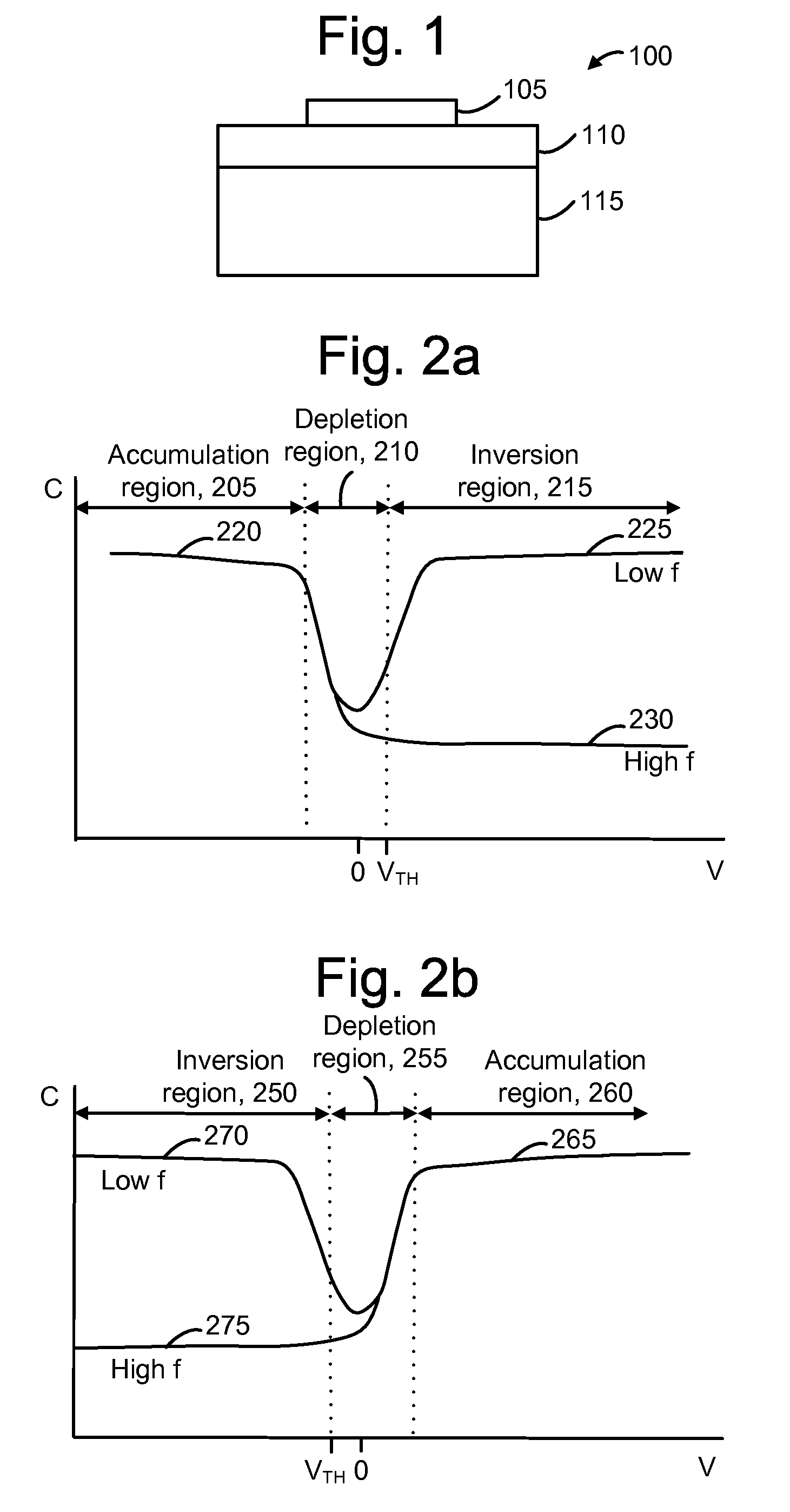
[0031]FIG. 1 depicts a MOS (metal oxide semiconductor) capacitor 100, also referred to as a MOSCAP. The capacitor 100 can be formed by depositing a layer of metallic conductive material 105 onto a layer of oxide 110 that has been deposited or grown on a layer of semiconductor material 115, such as a semiconductor wafer, referred to as the body. The semiconductor material 115 may be p-type or n-type, based on the polarity of the body, in which case the MOSCAP is referred to as being p-type or n-type, respectively. The MOSCAP is an example of a type of capacitor which includes an insulator layer between two conducting layers. Older MOSCAP designs used a metal such as aluminum for the top conducting layer. More recently, the top conductive layer has been formed from a material such as n+ or p+ polysilicon, which is conductive, although it is not a metal. For historical r...


PUM


Abstract

A charge pump with a MOS-type capacitor, where the MOS-type capacitor is operated in an inversion region in which capacitance varies as a function of the frequency of the applied signal. The charge pump is switched to transfer charge from an input node to the capacitor and from the capacitor to an output node. During a transition interval, a relatively high frequency switching signal is used to lower the capacitance and increase efficiency. During a settling interval, a relatively low frequency switching signal is used, in which case the capacitance is higher, but similar to a level which would be seen if the capacitor was operated in an accumulation region. MOS capacitor dimensions and switching intervals are mutually optimized to provide high efficiency and required throughput. The charge pump may be configured as a voltage multiplier, divider, inverter or follower, for instance.

Description

BACKGROUND OF THE INVENTION[0001]1. Field of the Invention[0002]The present invention relates to a charge pump.[0003]2. Description of the Related Art[0004]Electronic devices often require regulated voltages in order to operate properly. Typically, a supply voltage of the device is provided to a voltage regulator which can translate the voltage to an output voltage at different levels. Various types of voltage regulators can be used. For example, linear regulators provide a relatively noise free output and can be lower in cost, but are less efficient and unable to step-up or invert the input voltage. Switching regulators can be higher in cost but have greater efficiency and can provide step-up and inversion features. Switching regulators rapidly switch an energy storage device such as an inductor or capacitor on and off. A charge pump, or voltage converter, provides an output voltage which is different from the supply voltage. A charge pump typically uses capacitors as energy storag...

Claims


Application Information

Patent Timeline
Patent Type & Authority Patents(United States)
IPC IPC(8): G05F3/02
CPCH02M3/07
Inventor LIKHTEROV, BORIS
Owner WESTERN DIGITAL ISRAEL LTD
Learn More