Miniature magnetic-levitated lens driving device

a driving device and magnetic-levitate technology, applied in the direction of printers, instruments, camera focusing arrangement, etc., can solve the problems of primitive photography, uncompetitive price, bulky, etc., and achieve the effect of preventing dust contamination, reducing friction, and saving power

Inactive Publication Date: 2011-10-18
POWERGATE OPTICAL INC
View PDF10 Cites 35 Cited by
  • Summary
  • Abstract
  • Description
  • Claims
  • Application Information

AI Technical Summary

Benefits of technology

[0009]It is an objective of the present invention to provide a miniature magnetic-levitated lens driving device for magnetically suspending a lens module in a receiving space of a casing by magnetic suspension, so as to provide resistance to vibration, minimize friction, prevent dust contamination, and enable power saving by reducing the power consumed for driving the lens module.
[0010]In order to achieve aforementioned objective, the present invention discloses a miniature magnetic-levitated lens driving device which includes a lid, a casing, a lens module, a plate spring, and a magnetic-levitated module. The lid has a hollow structure and is coupled to the casing. The casing is formed therein with a receiving space. The lens module is provided in the receiving space. The plate spring is fixed between the lid and the casing and configured to resiliently confine the lens module to the receiving space. The magnetic-levitated module is provided in the receiving space and corresponds in position to the lens module. A magnetic repulsive force is produced by and between the magnetic-levitated module and the lens module, and in consequence the lens module is magnetically suspended in the receiving space formed by the lid and the casing, so as to save power, and minimize friction and microparticles.

Problems solved by technology

Hence, the conventional focusing lens is complicated in terms of its mechanical framework, difficult and intricate to assemble, bulky, expensive, power-consuming, and thus price-uncompetitive.
Primitive photography was complicated, as it required taking laborious steps, such as manual light metering, manual focusing, and automatic winding, and the laborious steps predisposed users to mistakes.
However, a zooming lens mechanically driven by a stepping motor has a drawback, that is, no chance of further miniaturizing the zooming lens, which is a factor in failure to miniaturize products.

Method used


Image

  • Miniature magnetic-levitated lens driving device
  • Miniature magnetic-levitated lens driving device
  • Miniature magnetic-levitated lens driving device

Examples


Embodiment Construction

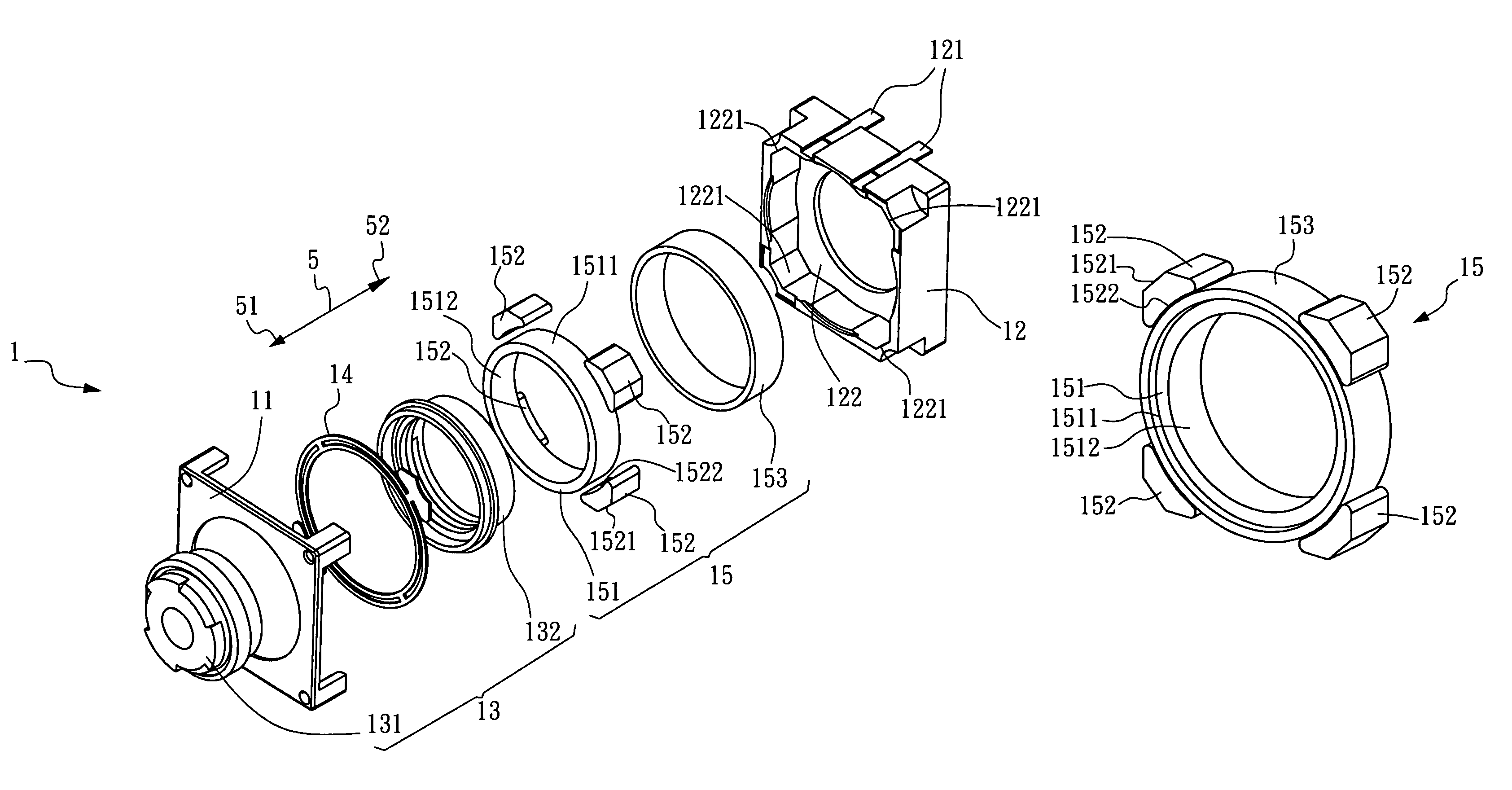
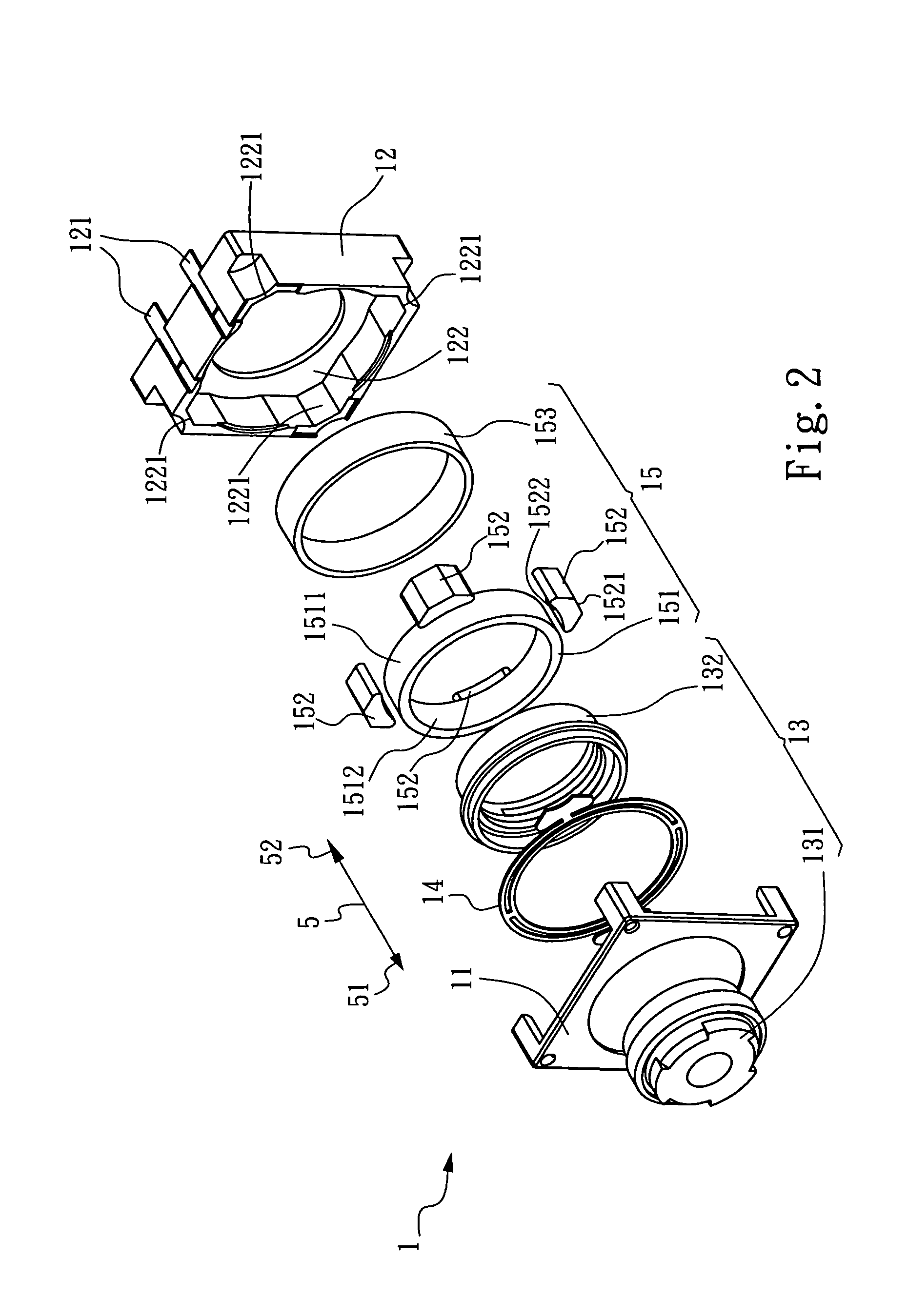
[0031]Referring to FIG. 2 and FIG. 3, there are shown an exploded perspective view and a perspective assembled view of a miniature magnetic-levitated lens driving device according to the present invention. As shown in the drawings, a miniature magnetic-levitated lens driving device 1 is defined with a central axis 5 and comprises a lid 11, a casing 12, a lens module 13, a plate spring 14, and a magnetic-levitated module 15. The central axis 5 is characterized by a forward direction 51 and a backward direction 52.

[0032]The lid 11 is of a hollow and annular structure. The casing 12 is of a hollow structure. At least a power source connecting line 121 is provided at a peripheral predetermined position of the casing 12. The lid 11 and the casing 12 are coupled to each other to thereby substantively form a receiving space 122 such that the receiving space 122 functions as a hollow core of the lid 11 and the casing 12 coupled together. A plurality of receiving recesses 1221 equidistantly ...


PUM


Abstract

A miniature magnetic-levitated lens driving device includes a lid, a casing, a lens module, a plate spring, and a magnetic-levitated module. The lid has a hollow structure and is coupled to the casing. The casing is formed therein with a receiving space. The lens module is provided in the receiving space. The plate spring is fixed between the lid and the casing and configured to resiliently confine the lens module to the receiving space. The magnetic-levitated module is provided in the receiving space and corresponds in position to the lens module. A magnetic repulsive force is produced by and between the magnetic-levitated module and the lens module, and in consequence the lens module is magnetically suspended in the receiving space formed by the lid and the casing, so as to save power, and minimize friction and microparticles.

Description

BACKGROUND OF INVENTION[0001]1. Field of the Invention[0002]The present invention relates to lens driving devices, and more particularly, to a miniature magnetic-levitated lens driving device wherein an optical lens module is magnetically suspended in a casing by a magnetic-levitated module and powered by an electromagnetic field.[0003]2. Description of the Prior Art[0004]Referring to FIG. 1, there is shown an exploded perspective view of a conventional focusing lens. As shown in the drawing, a mechanical-transmission focusing mechanism 9 for use with the conventional focusing lens comprises a high-cost high-precision driving component 91 (such as a stepping motor, ultrasonic motor, or piezoelectric actuator), a carrier 93 provided with a lens module 92 and driven by the driving component 91, and lots of transmission components. Hence, the conventional focusing lens is complicated in terms of its mechanical framework, difficult and intricate to assemble, bulky, expensive, power-cons...

Claims


Application Information

Patent Timeline
Patent Type & Authority Patents(United States)
IPC IPC(8): G02B7/02G03B3/10
CPCG02B7/08G02B7/026
Inventor CHANG, CHI LONEHSU, CHUAN YUHSU, WEN TSAIMENG, CHI TAI
Owner POWERGATE OPTICAL INC
Why Eureka
Try Eureka