Transmission optical fiber having large effective area

a technology of optical fiber and effective area, applied in the field of optical fiber transmission, can solve the problems of limited propagation of leakage modes, and achieve the effect of limiting bending and microbending losses and enlarge the effective area

Active Publication Date: 2011-10-18
DRAKA COMTEQ BV
View PDF13 Cites 45 Cited by
  • Summary
  • Abstract
  • Description
  • Claims
  • Application Information

AI Technical Summary

Benefits of technology

[0019]Accordingly, the present invention embraces an optical fiber profile that includes a central core, an intermediate cladding, and a depressed cladding. As compared with a typical standard single-mode fiber (SSMF) according to the ITU-T G.652 requirements, the central core is enlarged and flattened to thereby enlarge the effective area. The depressed cladding is sufficiently distant from the central core (i.e., separated by the intermediate cladding) to avoid strong perturbations of the fundamental mode. The depressed cladding is sufficiently buried and narrow to limit the bending and microbending losses and especially to control the cutoff wavelength. The propagation of leakage modes is also limited, if not avoided. The optical fiber according to the present invention has an effective area of more than 120 μm2 at 1550 nm with a cutoff wavelength that guarantees the single-mode operation of the optical fiber in the C band, while bending or microbending losses are comparable to a typical SSMF according to the ITU-T G.652 standards.

Problems solved by technology

The propagation of leakage modes is also limited, if not avoided.

Method used


Image

  • Transmission optical fiber having large effective area
  • Transmission optical fiber having large effective area
  • Transmission optical fiber having large effective area

Examples


Embodiment Construction

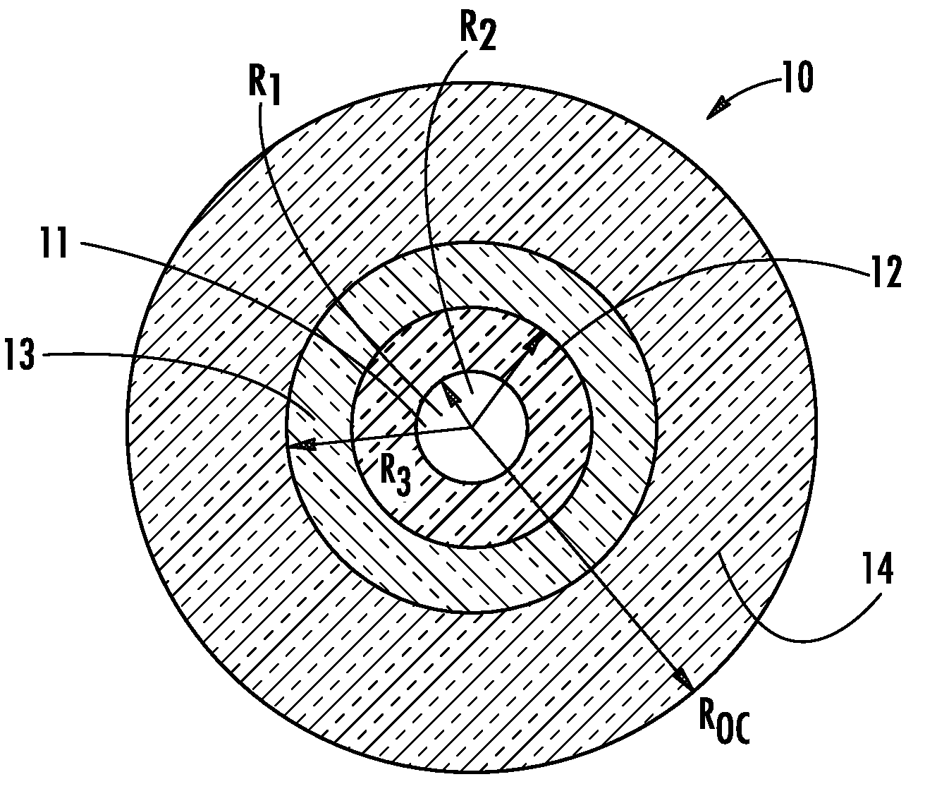
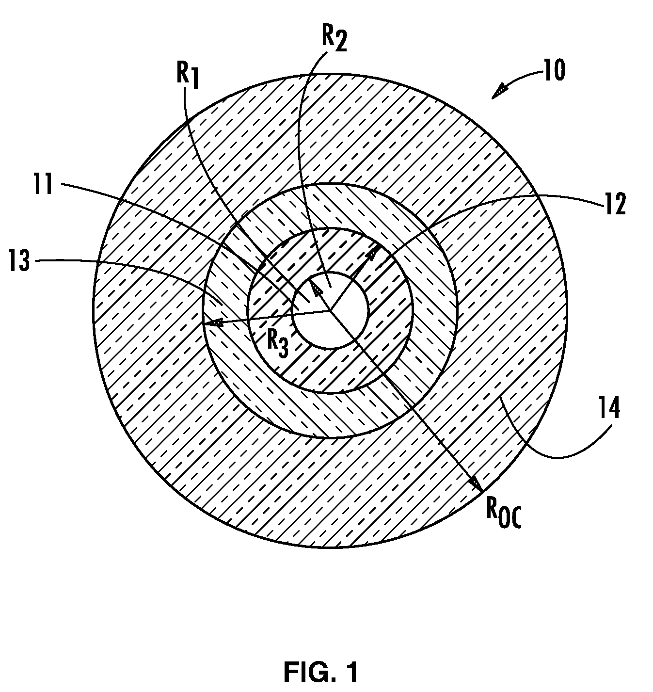
[0034]In one aspect (and with reference to FIG. 1), the present invention embraces a transmission optical fiber 10 that includes a core 11 having a radius r1 (i.e., the central core region in which the optical signal to be transmitted is guided) and a cladding region for confining the optical signal in the core 11. The cladding region includes a first inner cladding 12 (i.e., the “intermediate cladding” having a radius r2), a depressed second inner cladding (i.e., the “depressed cladding” having a radius r3), and an outer cladding 14 (e.g., an external optical cladding having a radius roc). The transmission optical fiber has (i) an effective area (Seff) of greater than about 120 μm2 as measured at a wavelength of 1550 nm and (ii) an effective cutoff wavelength (λCeff) of less than 1600 nm.

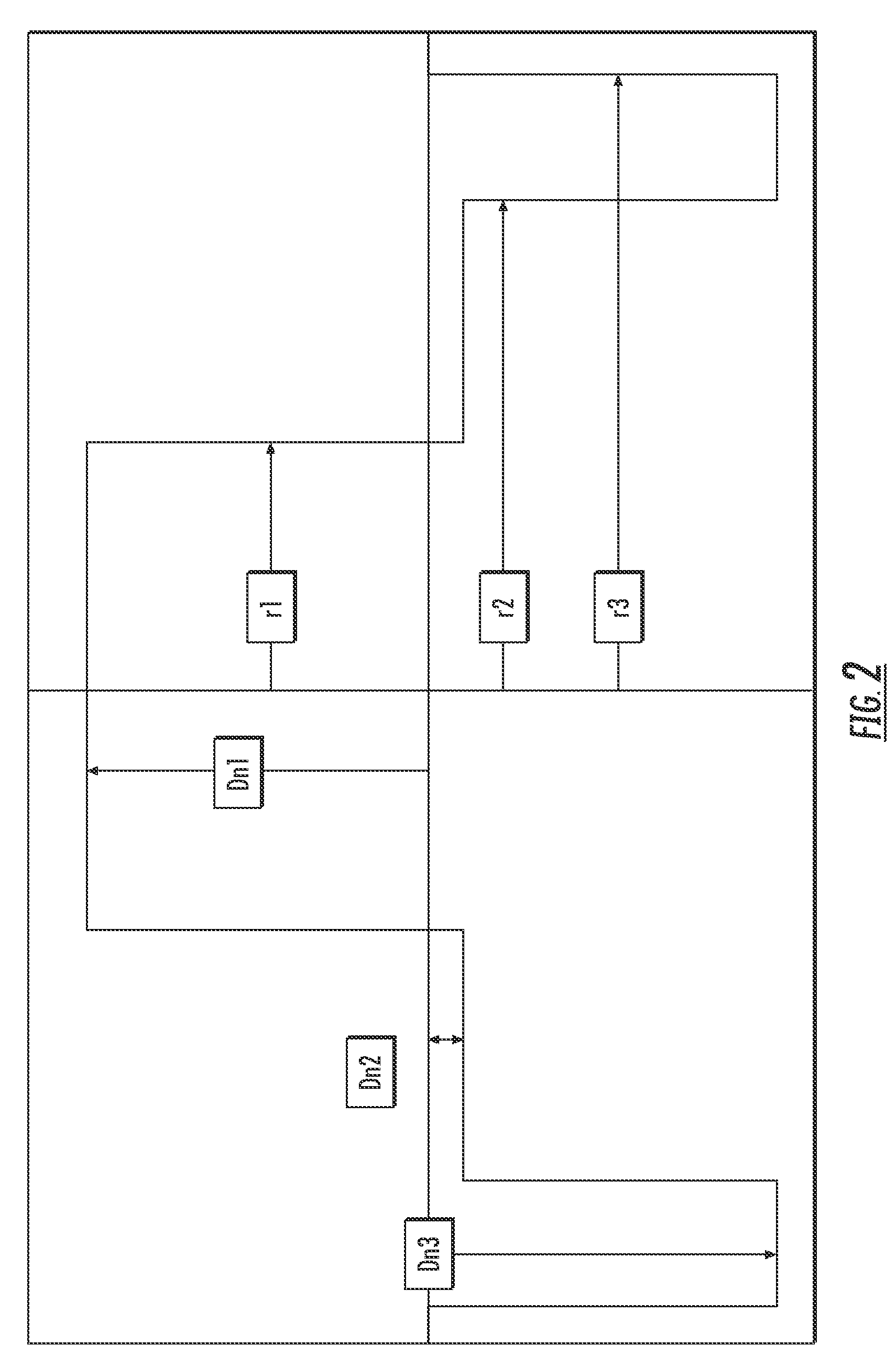
[0035]To define a nominal refractive index profile for an optical fiber, the index of the outer cladding is generally taken as a reference. The index values of the central core and of the claddings...


PUM


Abstract

The present invention relates to a transmission optical fiber. The optical fiber includes, from its center to its periphery a central core, an intermediate cladding, and a depressed cladding. The optical fiber has an effective area (Seff) of at least about 120 μm2 at a wavelength of 1550 nm and an effective cutoff wavelength (λCeff) of less than 1600 nm. The optical fiber has an effective area of more than 120 μm2 with a cutoff wavelength limited to less than about 1600 nm without degradation of other optical parameters (e.g., attenuation losses and dispersion).

Description

CROSS-REFERENCE TO PRIORITY APPLICATION[0001]This application claims the benefit of pending French application Ser. No. 07 / 02545 (filed Apr. 6, 2007, at the French Patent Office) via 35 U.S.C. §119. French application Ser. No. 07 / 02545 is hereby incorporated by reference in its entirety.FIELD OF THE INVENTION[0002]The present invention relates to the field of optical fiber transmission and, more specifically, to a line fiber having an enlarged effective area without increasing the bending and microbending losses.BACKGROUND OF THE INVENTION[0003]For optical fibers, the refractive index profile is generally qualified in relation to a graph, plotting refractive index as a function of optical fiber radius. Conventionally, the distance r to the center of the optical fiber is shown along the abscissa (i.e., the x axis), and the difference between the refractive index at radius r and the refractive index of the outer optical cladding of the optical fiber is shown along the ordinate axis (i...

Claims


Application Information

Patent Timeline
Patent Type & Authority Patents(United States)
IPC IPC(8): G02B6/028G02B6/00
CPCG02B6/02019G02B6/0365G02B6/02266
Inventor SILLARD, PIERREMOLIN, DENISDE MONTMORILLON, LOUIS-ANNEBIGOT-ASTRUC, MARIANNERICHARD, SIMON
Owner DRAKA COMTEQ BV
Why Eureka
Try Eureka